background image

7750C 

rev. 04/09/19

INSPECTION AND SETUP

 This is the safety alert symbol used for the SETUP INSTRUCTIONS section of this manual to alert you to potential personal injury 

hazards. Obey all instructions to avoid possible injury or death.

PLEASE REFER TO THE EXPLODED VIEW DRAWING IN THIS MANUAL IN ORDER TO IDENTIFY PARTS.

1.  Secure the fingers (#44) to the finger bases (#41) with the hardware (#27 and #35) provided.

2.  Loosely assemble the finger bases (#41) to the saddle plate (#52) as shown in the exploded view drawing.

3.  Secure one end of the chain (#51) to the saddle plate (#52). Connect the bolt (#34) to the saddle plate (#52) with the hardware (#27 and #35) 

provided. Slide the hook (#32) through the bolt (#34) and secure the hook with the wing nut (#33).

4.  Air may get trapped in the hydraulic system during freight and handling.


PURGING AIR FROM THE HYDRAULIC SYSTEM:


a.    Rotate the knob at the top of the hydraulic block in a clockwise direction until tight. 


      Now turn it in a counterclockwise direction two full turns. 


b.    Activate the hand pump about 15 times. 


c.    Rotate the release valve knob at the top of the hydraulic block in a clockwise direction until tight. 


d.    Activate the hand pump until the lift arm is raised to maximum height. You should experience a full pump stroke with each  

      incremental pump. 
 

e.    Repeat steps "a" through "d" until all air is purged from the system. 

OPERATING INSTRUCTIONS

 This is the safety alert symbol used for the OPERATING INSTRUCTIONS section of this manual to alert you to potential personal  

injury hazards. Obey all instructions to avoid possible injury or death.

1.  Lift the vehicle to the desired work height, and support the vehicle in accordance with the lift manufacturer's recommended lifting 

and support procedure

s.

2.  Position the transmission jack directly under the transmission. Turn the release valve knob all the way in a clockwise direction until 

it stops. Pump the handle, and the saddle assembly will start to rise. Raise the saddle to a height very close to the center of balance 
point of the transmission, but do not touch the transmission.

3.  Loosen the four bolts that secure the four fingers to the saddle. The fingers can be adjusted in and out to help position the 

transmission on the saddle. Now gently raise the saddle so it supports the transmission. Adjust the four fingers in position against 
the transmission, and tighten the bolts that secure the fingers to the saddle. Fore and aft saddle tilt adjustments are sometimes 
necessary to properly position the transmission on the saddle. Side to side tilt positioning may be necessary for the same reason 
and can be accomplished by activating the side to side tilt knob.

4.  The chain should be pulled over the center of balance portion of the transmission and secured on the chain hook. Rotate the  

wing nut to take up the slack in the chain and secure the transmission to the saddle.

5.  Remove the transmission from the engine according to instructions in the vehicle service manual.

6.  Once the transmission has been disconnected from the engine, very slowly turn the jack's release valve knob in a counterclockwise 

direction to make sure the jack's saddle and transmission do not hang up on any under vehicle components, wiring, fuel lines, etc. 
Continue to lower the jack all the way down.

7.  Remember to secure the transmission to the saddle before installing, and follow the vehicle manufacturer's installation instructions.

PREVENTATIVE MAINTENANCE


This is the safety alert symbol used for the PREVENTATIVE MAINTENANCE section of this manual to alert you to potential personal  


injury hazards. Obey all instructions to avoid possible injury or death.

1.  Always store the jack in a well protected area where it will not be exposed to inclement weather, corrosive vapors, abrasive dust, or any  


other harmful elements. The jack must be cleaned of water, snow, sand, grit, oil, grease or other foreign matter before using.

2.  The jack must be lubricated periodically in order to prevent premature wearing of parts. A general purpose grease must be applied to all  


zerk grease fittings, caster wheels, elevator arm, handle base pivot bolts, release mechanism and all other bearing surfaces. Jacks found  


to be defective due to worn parts resulting from inadequate or no lubrication are not eligible for warranty consideration.

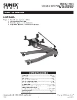
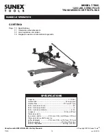
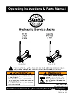
OWNER'S MANUAL

MODEL 7750C

1200 LBS. LOW PROFILE

TRANSMISSION JACK

Содержание 7750C

Страница 1: ...2019 Sunex Tools SPECIFICATIONS OWNER S MANUAL MODEL 7750C 1200 LBS LOW PROFILE TRANSMISSION JACK Capacity 1 200 lbs Min Height 6 3 Max Height 31 1 Saddle Forward Tilt 55 Saddle Backward Tilt 8 Saddle Lateral Tilt 6 18 Overall Length 37 Saddle Base Size 9 25 x 9 25 Saddle Base Size with Fingers Extended 13 2 x 13 2 Product Weight 113 5 lbs Shipping Weight 119 lbs Complies with ASME PASE 2014 Safet...
Страница 2: ...aulic fluid or unstable due to loose or missing components Make corrections before using Consult the vehicle manufacturer for the transmission s center of balance Secure the transmission to the jack s saddle with the anchorage restraint system provided before raising or lowering the transmission Center load on saddle Be sure setup is stable before working on vehicle Never use a power tool to activ...

Страница 3: ...our bolts that secure the four fingers to the saddle The fingers can be adjusted in and out to help position the transmission on the saddle Now gently raise the saddle so it supports the transmission Adjust the four fingers in position against the transmission and tighten the bolts that secure the fingers to the saddle Fore and aft saddle tilt adjustments are sometimes necessary to properly positi...

Страница 4: ...PPING ADDRESS Sunex Tools 315 Hawkins Rd Travelers Rest South Carolina 29690 MAILING ADDRESS Sunex Tools P O Box 1233 Travelers Rest South Carolina 29690 LIMITED WARRANTY TROUBLESHOOTING PROBLEM ACTION 1 Unit will not lift rated load Purge air from hydraulic system by following procedure under SETUP 2 Unit will not sustain rated load or feels spongy under rated load Purge air from hydraulic system...

Страница 5: ...g 1 20 Washer 16 4 21 Connect Axle 1 22 Lift Arm Assembly 1 23 Link Rod 2 24 Pin 4 10 2 25 Threaded Trunnion 1 26 Bearings 2 27 Washer 10 7 28 Nut M10 1 REF PART DESCRIPTION QTY 28 Nut M10 1 29 Slave Trunnion 1 30 Cotter Pin 2 25 1 31 Adjusting Screw Rod 1 32 Hook 1 33 Wing Nut M6 1 34 Bolt 1 35 Nut M10 6 36 Adjusting Screw Rod 1 37 Stop Bushing 1 38 Nut M12 2 39 Washer 22 2 40 Trunnion 1 41 Finge...

Страница 6: ... OPERATIÓN MODEL 7750C 1200 LBS GATO PARA TRANSMISIÓN DE BAJO PERFIL Capacidad 1 200 lbs Mín Altura 6 3 Máx Altura 31 1 Asiento Inclinación Frontal 55 Asiento Inclinación Trasera 8 Asiento Inclinación Lateral 6 18 Longitud Global 37 Dimensiones de la base del asient 9 25 x 9 25 Dimensiones de la base del asiento con las garras extendidas 13 2 x 13 2 Peso del Producto 113 5 lbs Peso del Envío 119 l...

Страница 7: ... correcciones antes del uso Consulte el fabricante del vehículo para el centro de equilibrio de la transmisión Nunca use una herramienta neumática para activar los tornillos de inclinación de montura Opere manualmente o con una llave de cubo Asegure la transmisión sobre la silla del gato con el sistema de restricción de anclaje provisto antes de levantar o bajar la transmisión Centre la carga sobr...

Страница 8: ...mpletamente en el sentido de las agujas del reloj hasta que deje de girar Bombee la manivela y el ensamble de la silla se comience a elevar Eleve la silla hasta una altura muy cercana al centro del punto de equilibrio de la transmisión pero no toque la transmisión 3 Afloje los cuatro pernos los que sujetan los cuatro dedos a la silla Los dedos pueden ajustarse hacia adentro y hacia fuera para asis...

Страница 9: ...licas o partes desajustadas o faltantes Tome las medidas de corrección apropiadas antes de usar el gato otra vez 6 No haga ningún Intento para hacer ninguna reparación hidráulica al menos que usted sea un Individuo calificado de reparación hidráulica y que esté familiarizado con este equipo Las reparaciones deben llevarse a cabo por parte de un centro de servicio autorizado SUNEX INTERNATIONAL INC...

Страница 10: ...ÉCIFICATIONS Capacité 1 200 lbs Hauteur Min 16 cm 6 3 po Hauteur Max 77 5 cm 31 1 po Selle Inclinaison Avant 55 Selle Inclinaison Arrière 8 Selle Inclinaison Latérale 6 18 Longueur 93 9 cm 37 po Dimensions de la base de la sellette 23 5 cm x 23 5 cm 9 25 po x 9 25 po Dimensions de la sellette avec les griffes déployées 33 5 cm x 33 5 cm 13 2 po x 13 2 po Poids du produit 51 5 Kg 113 5 lbs Poids à ...

Страница 11: ...able en raison de pièces manquantes ou lâches Apporter les correctifs requis ou les réparations nécessaires avant l utilisation Consulter le fabricant du véhicule pour connaître le centre de gravité de la transmission N utilisez jamais d outil électrique pour modifier les vis à incliner la selle Faites le manuellement ou à l aide d une clé à douilles Bien fixer la transmission à la selle du cric à...

Страница 12: ... fabricant du vérin 2 Positionnez le vérin de transmission directement sous la transmission Tournez le bouton de la soupape de relâchement dans le sens horaire jusqu à ce qu il s arrête Pompez la poignée et la selle commencera se soulever Soulevez la selle très près du centre du point d équilibre de la transmission mais ne touchez pas la transmission 3 Desserrer les quatre boulons qui maintiennent...

Страница 13: ...auteur complète Purger l air du système hydraulique comme mentionné ci dessus ou vérifier le niveau de l huile dans le réservoir 4 La poignée tend à augmenter vers le haut tandis que l unité est sous la charge Pompez la poignée rapidement plusieurs fois de pousser l huile après des robinets à tournant sphérique dans l unité de puissance 5 L unité ne fonctionne toujours pas Veuillez communiquer ave...

Отзывы: