34
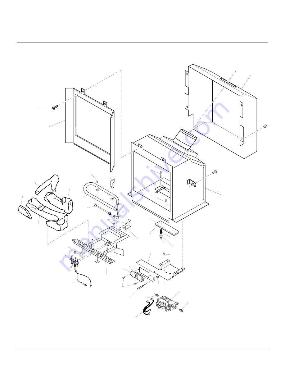
CAST IRON STOVE AND BURNER SYSTEM
106021
SUN VALLEY STOVE COMPANY
ILLUSTRATEDPARTSBREAKDOWN
MSDVBNMSDVBP
LO
H
I
P
IL
O
T
OFF
ON
24
27
19
20
21
23
26-1
26-4
26-2
26-3
29
30
4
25
1
2
7
8
9
10
11
13
12
31
15
16
17
18
22
28
5
32
3
14
6
Страница 1: ...lt a qualified installer ser vice agency or the gas supplier WARNING If the information in this manual is not followed exactly a fire or explosion may result causing property damage personal in jury or loss of life FOR YOUR SAFETY Do not store or use gasoline or other flammable vapors and liquids in the vicinity of this or any other appliance Installation and service must be performed by a qualifi...
Страница 2: ...li fied service person The glass door must be properly seated and sealed If this unit is not properly installed by a qualified service person with glass door properly seated and sealed gas leakage can occur CarbonMonoxidePoisoning Earlysignsof carbon monoxide poisoning resemble the flu with headaches dizziness or nausea If you havethesesigns thestovewithburnersystem may not have been installed pro...
Страница 3: ...urner system has a piezo ignitor This system requires no matches batteries or other sources to light burner system Figure 1 Sun Valley Direct Vent Burner System Shown Installed in Approved Sun Valley Cast Iron Stove Body Models MC Series Only GLOSSARY OF TERMS Chase A boxlike enclosure to protect venting from the elements when the venting run is on the outside of a structure Mastic Apliablesealant...
Страница 4: ...tained see Figure 3 and Figure 4 on page 5 4 This stove is a freestanding unit de signed to set directly on the floor If your stove is to be installed directly on carpeting vinyl tile or any combustible material other than wood it must be installed on a metal or wood panel ex tending the full width and depth of the stove See Figure 5 page 5 PRE INSTALLATION PREPARATION 6 4 Front 4 36 from Front 42...
Страница 5: ...tove On Side Figure 8 Removing Pallet Wood From The Bottom of The Stove Figure 9 Locating Threaded Holes for Stove Bottom Legs and Door Attach ment Figure 6 Removing Back Panel Bolt Product Identification Label Back Stove Panel Pallet Wood Bolt Pallet Wood Bottom Of Stove Unit Front Door Hinge Step Bolt Hole Door Catch Bolt With Adjustable Hex Nuts Hole Leg Hole Leg Hole Leg Hole Stove Bottom Hole...
Страница 6: ...at washer and lock washer with each bolt Tighten bolts into threaded holes on stove body see Figure 10 and Figure 9 on page 5 Use an adjustable wrench or a 12mm socket 9 Optional Fasten stove bottom to stove with four 4 M6 x 1 25mm bolts Use a flat washer and lock washer with each bolt Tighten bolts into threaded holes on stove body see Figure 11 and Fig ure 9 on page 5 Use an adjustable wrench or...
Страница 7: ...R SYSTEM ASSEMBLY Continued Figure 16 Removing Metal Plate from Stove Body Bracket Screw Stove Body Metal Plate INSTALLING OPTIONAL BLOWER ACCESSORY NOTICE If installing blower in an existingstoveburnersystemwith gasconnections shutoffgassup ply and disconnect burner sys tem from gas supply Contact a qualifiedservicepersontodothis Attaching Thermal Switch to DA3610T Thermostatically Controlled Blo...
Страница 8: ...er motor and thermal switch where applicable are securely attached and that the screw retaining the green ground wire is tight WARNING A qualified ser vicepersonmustconnectburner system to gas supply Follow all local codes Figure 19 Installing Optional Blower Accessory Thermostat Model DA3610T Shown CAST IRON STOVE AND DIRECT VENT BURNER SYSTEM ASSEMBLY Continued 3 Placespeedcontrolon left inside ...
Страница 9: ...y Screw CAST IRON STOVE AND DIRECT VENT BURNER SYSTEM ASSEMBLY Continued Continued If your house is covered with vinyl sid ing you will need to use a vinyl siding standoff see Figure 27 page 13 Install horizontal venting with a 1 4 rise for every 12 of run toward the termination You may paint the vent terminal with 450ºF 232ºC heat resistant paint to co ordinate with the exterior finish There must...
Страница 10: ...ove paved side walk or a paved driveway located on public property 84 inches 2133mm minimum M clearance under veranda porch deck 12 inches 305mm minimum N clearance above a roof shall extend a minimum of 24 inches 610mm above the highest point when it passes through the roof surface and any other obstruction within a horizontal distance of 18 inches 457mm vent shall not terminate directly above a ...
Страница 11: ...SA International Installation other than as instructed by these instructions INSTALLATION PLANNING There are two basic types of direct vent installation Horizontal Termination Vertical Termination It is important to select the proper length of vent pipe for the type of termination you choose It is also important to note the wall thickness For Horizontal Termination Select the amount of vertical ri...
Страница 12: ...nd the snorkel termination 2 Rigid vent pipes and fittings have spe cial twist lock connections Assemble the desired combination of pipe and el bows to the appliance adaptor with pipe seams oriented towards the wall or floor Twist lock Procedure The female ends of the pipes and fittings have four locking lugs indentations These lugs will slide straightintomatchingslotsonthemaleends ofadjacentpipes...
Страница 13: ...combustibles is maintained At tach the vent cap with four wood screws supplied see Figure 26 Note Re place the wood screws with appropri ate fasteners for stucco brick concrete or other types of siding For vinyl siding stucco or wood exte rior use vinyl siding standoffs between ventcapandexteriorwall Thevinylsid ing standoff prevents excessive heat from melting the vinyl siding material Bolt the v...
Страница 14: ...differ entconfigurationsforventingwithhorizon tal termination Each figure includes a chart with vertical minimum maximum and hori zontalmaximumdimensionswhichmustbe met Seal all connections with high tem peraturesiliconesealant outerpipeonly as specified in the second warning statement on page 11 All horizontal terminations re quire 1 4 rise per 12 of horizontal run UP UP Venting with Two 90 Elbow...
Страница 15: ...g loadbearing members Note Pay spe cial attention to these installation in structions for required clearances air space to combustibles when passing through ceilings walls roofs enclo sures attic rafters etc Do not pack air spaces with insulation Also note maxi mum vertical rise of the venting sys tem and any maximum horizontal off set limitations Offsets must fall within the parameters shown in F...
Страница 16: ... vent pipe and seal outer pipe connection with high temperature sili cone sealant as specified in the second warning statement on page 11 Note If the vent pipe passes through any occupiedareasabovethefirstfloor including storage spaces and closets you must enclose pipe Youmayframeandsheetrocktheenclo surewithstandardconstructionmaterial Make sure and meet the minimum allowable clear ances to combu...
Страница 17: ...i conesealantasspecifiedinthesecondwarn ing statement on page 11 Venting with Two 90 Elbows Vertical V Horizontal H1 Horizontal H2 5 min 2 max 6 min 4 max 7 min 6 max 8 min 8 max 20 max 8 max Figure 37 Vertical Rigid Venting Configuration Using Two 90 Elbows with Two Horizontal Runs Venting with One 90 Elbow Vertical V Horizontal H 5 min 2 max 6 min 4 max 7 min 6 max 8 min 8 max 20 max 8 max Figur...
Страница 18: ...icone Ver tical Termination and 26 screws D1000BK 7 x 12 Black Coaxial Pipe 1 pk D1010BK 7 x 24 Black Coaxial Pipe 1 pk D1020BK 7 x 48 Black Coaxial Pipe 1 pk D1030BK 7 Adjustable 7 12 Black Coaxial Pipe 1 pk D1050BK 7 x6 BlackCoaxialPipe 1pk D2000BK 7 X 90 Elbow 1 pk D2010BK 7 x 45 Elbow 1 pk D2020BK 7 x 30 Elbow D2030BK 7 x 60 Elbow D3000 Wall Strap Offset Support 6 pcs D3010 Storm Collar 6 pcs ...
Страница 19: ...ne with gas con nector if allowed by local codes not provided AnA G A design certifiedmanualshutoff valve with 1 8 NPT tap is an acceptable alternative to test gauge connection Pur chase the A G A design certified manual shutoff valve from your dealer WARNING A qualified ser vicepersonmustconnectburner system to gas supply Follow all local codes CAUTION For propane LP units never connect burner sy...
Страница 20: ...to gas supply Check re connected fittings for leaks CHECKING GAS CONNECTIONS WARNING Test all gas pip ing and connections for leaks after installing or servicing Cor rect all leaks at once WARNING Neveruseanopen flame to check for a leak Apply commercial leak test solution to all gas joints Bubbles forming show a leak Correct all leaks at once CONNECTING STOVE BURNER SYSTEM TO GAS SUPPLY Installat...
Страница 21: ... 2 Open propane LPsupply tank valve for propane LPburner system or main gas valve located on or near gas meter for natural gas burner system 3 Make sure control knob of burner sys tem is in the OFF position 4 Check all joints from manual shutoff valve to thermostat gas valve see Fig ure 44 for propane LP or Figure 45 for natural Apply commercial leak test so lution to all gas joints Bubbles formin...
Страница 22: ...n where there is good air circulation Avoid heat sources such as lamps direct sun light fireplace or heat and air condi tioning ducts WARNING Do not connect this thermostat to a power source Electrical shock and or fire hazard will occur 5 Gently remove the cover of the ther mostat from the base Grasp the sides of the cover firmly and pull to separate from the base 6 Feed the electrical wires thro...
Страница 23: ... Discard switch plate screws and nuts 4 Install battery into receiver battery clip andconnecttoterminals seeFigure50 5 Place receiver into valve bracket and align holes see Figure 51 6 Use push in fasteners included with receiver to secure to bracket 7 Connect the wires from the receiver to the valve at TH and THTP see Figure 46 page 22 Figure 53 Removing Front Panel from Stove Figure 50 Installin...
Страница 24: ...ng Log No 1 Figure 56 Installing Log No 2 Figure 57 Installing Log No 3 Figure 58 Installing Log No 4 WARNING The glass door must be securely in place before running this burner system Do notrunthisburnersystemifglass is missing or broken NOTICE Do not put lava rock on burner or under burner Placing lava rock on burner could cause performance problems the rear log as shown in Figure 57 4 Place log...
Страница 25: ... turn the gas control knob Never use tools If the knob will not push in or turn by hand don t try to repair it call a qualified service technician Force or attempted repair may result in a fire or explosion D Do not use this appliance if any part has been under water Immediately call a qualified service technician to inspect the appliance and to replace any part of the control system and any gas c...
Страница 26: ...sing the ON or OFF buttons on the hand held remote control unit Figure 61 Setting the Selector Switch Gas Control Knob and Variable Control Knob for Remote Operation TEMP STATUS HI LO MAN ON AUTO OFF Figure 62 Hand Held Thermostat Remote Control Unit Selections GHRCT Only Shows Temperature Setting Allows Burners to be Turned On and Off with the Hand Held Remote Unit The Burner System will Automati...
Страница 27: ...ch bracket to the left just inside the door Both the GA3700 manual blower and the DA3610T thermostatically controlled blower have an ON setting and an OFF setting The blower will only run when the switch is in the ON position In the OFF position the blower will not operate NoteforDA3610TOnly Ifyouareusing DA3610T blower with optional thermo stat wallmountorremotecontrol forthe burner system your b...
Страница 28: ...RNING Only parts sup pliedbythemanufacturershould be used when replacing broken ordamagedglassdoorpanel see ReplacementParts page32 This glass door panel is a complete unit No substitute materials may be used If glass has been broken carefully remove glass door see Removing Replacing Glass Door page 23 Vacuum all glass pieces with a shop vac CAUTION Wear gloves and safety glasses while handling or...
Страница 29: ...le connection loose at con trol valve 6 Thermocouple damaged 7 Control valve damaged REMEDY 1 Reconnect ignitor cable 2 Free ignitor cable if pinched by any metal or tubing Keep ignitor cable dry 3 Tighten nut holding piezo ignitor Nut is located behind the mounting bracket 4 Replace ignitor cable 5 Replace piezo ignitor 6 Replace pilot assembly 7 Replace pilot assembly 1 Turn on gas supply or ope...
Страница 30: ...perate burner until air is removed from line Have gas line checked by local pro pane LP or natural gas company 3 Clean burner see Cleaning and Maintenance page 28 or replace burner orifice 1 Adjust the log set so that the flame does not excessively impinge on it 2 Inspect the opening at the base of the burner to see that it is NOT packed with any type of material 1 This is common If noise is exces...
Страница 31: ...tive 1 Gas leak See Warning statement above 1 Improper log placement 2 Air holes at burner inlet blocked 3 Burner flame holes blocked OBSERVED PROBLEM Burner system produces unwanted odors Burner system shuts off in use Gas odor even when control knob is in OFF position Gas odor during combustion Dark residue on logs or inside of burner system REMEDY 1 Locate and correct all leaks see Check ing Ga...
Страница 32: ...icing controls Wiringerrorscancause improper and dangerous opera tion Verify proper operation af ter servicing Note Use only original replacement parts Thiswillprotectyourwarrantycoveragefor parts replaced under warranty PARTS UNDER WARRANTY Contact authorized dealers of this product If they can not supply original replacement part s call DESA International s Techni cal Service Department at 1 800...
Страница 33: ...nual MANUAL BLOWER KIT GA3700 Manual variable control blower accessory for both the MDVBN and MSDVBP Series burner systems THERMOSTATICALLY CONTROLLED BLOWER KIT DA3610T Provides better heat distribution Blower turns off and on automatically as needed Completeinstallationandoperationinstruc tions included in this manual RECEIVER AND HAND HELD REMOTE CONTROL KIT GHRC SERIES For all models Allows th...
Страница 34: ... BURNER SYSTEM 106021 SUN VALLEY STOVE COMPANY ILLUSTRATED PARTS BREAKDOWN MSDVBN MSDVBP LO H I P I L O T OFF ON 24 27 19 20 21 23 26 1 26 4 26 2 26 3 29 30 4 25 1 2 4 4 7 8 9 10 11 13 12 31 15 16 17 18 22 22 28 5 32 3 14 6 ...
Страница 35: ...01 Burner Natural 1 105523 02 Burner Propane LP 1 20 104506 16 Orifice Natural 1 104506 17 Orifice Propane LP 1 21 104507 01 Brass Elbow 1 22 104508 01 Brass Fitting 2 23 105493 01 Aluminum Tubing Assy 1 24 104510 01 Pilot Tubing Assembly 1 25 105325 01 Air Deflector 1 26 105491 01 Log Set 1 26 1 105774 01 Rear Log 1 26 2 105774 02 Front Log 1 26 3 105774 03 Crossover Log 1 26 4 105774 04 Log Piec...
Страница 36: ...VE AND BURNER SYSTEM 106021 SUN VALLEY STOVE COMPANY ILLUSTRATED PARTS BREAKDOWN SUN VALLEY STOVE MC SERIES Indicates Color Suffix Designation 1R 1C 1L 5 8 10 8 7 4 6 5 5 7 1 7 2 5 4 7 3 2 3 9 Discarded During Assembly ...
Страница 37: ...elain Enamel Green 4 Total Per Stove 1 104175 15 One Leg Porcelain Enamel Red 4 Total Per Stove 1 6 104176 01 Leg Leveler bolt M8 x 1 25 55mm Long 4 Total Per Stove 1 7 104177 02 Hardware Kit 1 7 1 Door Hinge Step Bolt With Shoulder 1 Per Unit 1 7 2 Door Catch Bolt M8 x 1 25 55mm Long With Two M8 Hex Nuts 1 Per Unit 1 7 3 Bottom Floor Bolts M6 x 1 25mm Long With Flat Washer And Lock Washer 4 Per U...
Страница 38: ...Failure to use original factory replacement parts voids this warranty The stove and burner system MUST be installed by a qualified installer in accordance with all local codes and instructions furnished with the unit This warranty does not apply to parts that are not in original condition because of normal wear and tear or parts that fail or become damaged as a result of misuse accidents lack of p...