background image

Chapter 2

System Setup

33

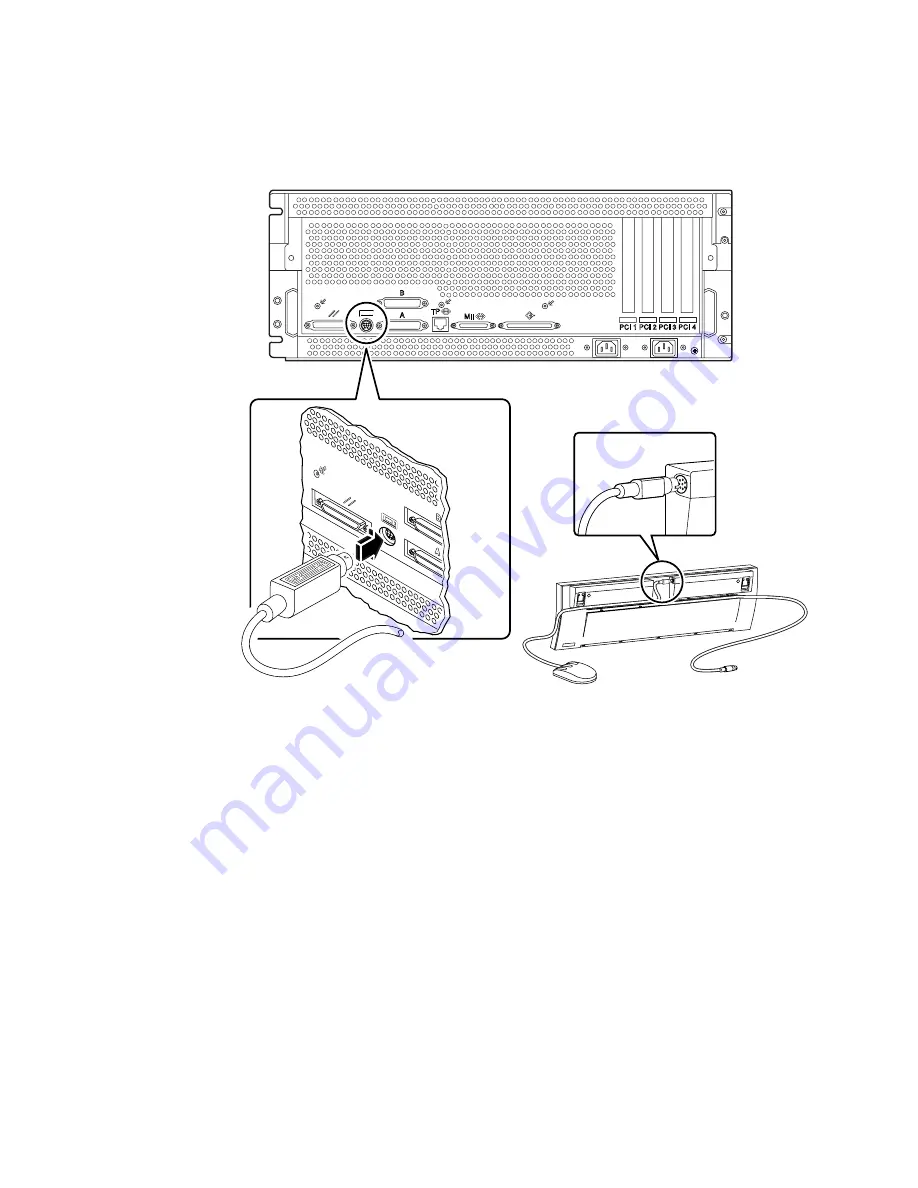
4. Connect the keyboard cable to the server’s keyboard/mouse port.

5. Connect the mouse cable to the appropriate receptacle on the keyboard.

What Next

You can now issue system commands from the keyboard and view system messages.
Continue with your installation or diagnostic procedure as needed.

Содержание Sun Enterprise 220R

Страница 1: ...erver Owner s Guide Part No 806 1079 10 Revision A October 1999 Sun Microsystems Inc 901 San Antonio Road Palo Alto CA 94303 4900 USA 650 960 1300 Fax 650 969 9131 Send comments about this document to...

Страница 2: ...right 1999 Sun Microsystems Inc 901 San Antonio Road Palo Alto Californie 94303 4900 U S A Tous droits r serv s Ce produit ou document est prot g par un copyright et distribu avec des licences qui en...

Страница 3: ...ence when the equipment is operated in a commercial environment This equipment generates uses and can radiate radio frequency energy and if it is not installed and used in accordance with the instruct...

Страница 4: ...iv Sun Enterprise 220R Server Owner s Guide October 1999 BSMI Class A Notice The following statement is applicable to products shipped to Taiwan and marked as Class A on the product compliance label...

Страница 5: ...lies with all the requirements for the CE Mark when connected to a Sun workstation or server EN55022 CISPR22 1985 Class A Curtis Straus LLC Report No E990551 1 EN50082 1 IEC801 2 1991 8 kV Direct 15kV...

Страница 6: ...vi Sun Enterprise 220R Server Owner s Guide October 1999...

Страница 7: ...symbols may be used Modifications to Equipment Do not make mechanical or electrical modifications to the equipment Sun Microsystems is not responsible for regulatory compliance of a modified Sun prod...

Страница 8: ...s as a standby type device only The power cord serves as the primary disconnect device for the system Be sure to plug the power cord into a grounded power outlet that is nearby the system and is readi...

Страница 9: ...n an den Ger ten vor Sun Microsystems bernimmt bei einem Sun Produkt das ge ndert wurde keine Verantwortung f r die Einhaltung beh rdlicher Vorschriften Aufstellung von Sun Ger ten Einhaltung der SELV...

Страница 10: ...hgerecht verlegte geerdete Steckdose an Achtung Der Ein Aus Schalter dieses Ger ts schaltet nur auf Wartezustand Stand By Modus Um die Stromzufuhr zum Ger t vollst ndig zu unterbrechen m ssen Sie das...

Страница 11: ...symboles utilis s Un des symboles suivants sera peut tre utilis en fonction du type d interrupteur de votre syst me Modification du mat riel Ne pas apporter de modification m canique ou lectrique au...

Страница 12: ...tation ou un lectricien qualifi Attention tous les cordons d alimentation n ont pas forc ment la m me puissance nominale en mati re de courant Les rallonges d usage domestique n offrent pas de protect...

Страница 13: ...cortocircuitos que provoquen un incendio descargas el ctricas o da os en el equipo S mbolos En este libro aparecen los siguientes s mbolos Attention Les unit s Product Name contiennent une batterie t...

Страница 14: ...a fiabilidad de funcionamiento de su producto Sun y para protegerlo de sobrecalentamien tos no deben obstruirse o taparse las rejillas del equipo Los productos Sun nunca deben situarse cerca de radiad...

Страница 15: ...8 XXXPCZ M48T59W XXXPCZ o MK48T08 Las bater as no son elementos reemplazables por el propio cliente Pueden explotar si se manipulan de forma err nea No arroje las bater as al fuego No las abra o inten...

Страница 16: ...n Kassera anv nt batteri enligt fabrikantens instruktion ADVARSEL Litiumbatteri Eksplosionsfare ved fejlagtig h ndtering Udskiftning m kun ske med batteri af samme fabrikat og type Lev r det brugte ba...

Страница 17: ...220R Server 1 Locating Front Panel Features 4 Locating Back Panel Features 6 About the Status and Control Panel 7 Keyswitch Settings 8 System LED Indicators 9 2 System Setup 11 About the Parts Shippe...

Страница 18: ...terface Options 46 How to Configure the Standard Ethernet Interface 47 How to Add an Ethernet Interface 49 How to Attach a Twisted Pair Ethernet TPE Cable 52 How to Attach an MII Ethernet Transceiver...

Страница 19: ...D 0 72 Disk Striping With Parity RAID 5 72 Hot Spares 72 Hot Plug 73 About Internal Disk Drives 74 Configuration Rules 75 About Power Supplies 76 About the Standard Ethernet Port 78 About the Serial P...

Страница 20: ...Emergency 108 About the Tape Drive and Tape Cartridges 110 Handling and Storing Tape Cartridges 110 Thermal Conditioning 110 How to Insert a Tape Cartridge 111 How to Remove a Tape Cartridge 113 How...

Страница 21: ...roubleshooting Your System 138 Error Indications 138 Software Commands 143 About Diagnosing Specific Problems 147 Network Communications Failure 147 Power On Failure 149 Video Output Failure 149 Disk...

Страница 22: ...xxii Sun Enterprise 220R Server Owner s Guide October 1999...

Страница 23: ...headings and you ll find the cue words that direct you to the categories of questions and answers such as How to How do I do something About Is there more information about this topic Reference for W...

Страница 24: ...administrative information and tasks associated with the configuring of Ethernet interfaces and on booting a PCI based Ethernet system Chapter elemparanumonly elemtext describes the hardware configura...

Страница 25: ...h your system Typographic and Command Entry Conventions Typeface or Symbol Meaning Examples AaBbCc123 The names of commands files and directories on screen computer output Edit your login file Use ls...

Страница 26: ...n Microsystems service providers Late breaking product news and information Sun Enterprise 220R Server Setup and Rackmounting Guide Sun Enterprise 220R Server Service Manual Sun Enterprise 220R Server...

Страница 27: ...docs sun com archive or search for a specific book title or subject at http docs sun com Sun Welcomes Your Comments We are interested in improving our documentation and welcome your comments and sugge...

Страница 28: ...xxviii Sun Enterprise 220R Server Owner s Guide October 1999...

Страница 29: ...nding overall system performance The system is housed in a standard Electronic Industries Association 310 EIA 310 specification compliant rackmountable enclosure The enclosure measures 7 00 inches hig...

Страница 30: ...k Drives on page 74 External multi disk storage subsystems and Redundant Arrays of Inexpensive Disks RAID storage arrays can be supported by installing single channel or multi channel PCI host adapter...

Страница 31: ...ations with two power supplies provide both redundancy and full hot swap capability For more information about the power supplies see About Power Supplies on page 76 The Sun Enterprise 220R server has...

Страница 32: ...o controls the system cover lock on the top of the system see page 91 If you lose the key contact your Sun sales representative about replacing the key The system s Power button is beside the keyswitc...

Страница 33: ...tem front doors are open Each power supply has an LED that displays the AC power DC power and fault status of the supply Power supplies are accessible only to qualified service providers See Power Sup...

Страница 34: ...k panel A ground screw hole 0 157 inches in diameter and 0 236 inches deep 4 mm x 6 mm is located in the lower right corner of the back panel Contact your Sun sales representative if you need a ground...

Страница 35: ...7 About the Status and Control Panel The status and control panel includes two LED indicators and a three position security keyswitch LED indicators Power button Locked position Standby position Keysw...

Страница 36: ...on down for five seconds while the keyswitch is in this positon will cause an immediate hardware power off Locked This setting disables the system s Power button and also locks the front doors prevent...

Страница 37: ...ystem the fault indicator remains lit whether the system is in normal operating mode or is switched to Standby mode using the keyswitch When you first power on the system the LEDs are individually tog...

Страница 38: ...10 Sun Enterprise 220R Server Owner s Guide October 1999...

Страница 39: ...ion is covered in this chapter About the Parts Shipped to You on page 12 About Server Rackmounting on page 18 About Communicating With the Server on page 28 Tasks covered in this chapter include How t...

Страница 40: ...tents and packing material for the agent s inspection Save the original shipping containers and packing materials in case you need to store or ship your system If you cannot store the shipping materia...

Страница 41: ...r background information about network support see About Network Interface Options on page 46 How do you want to use configure your machine s internal disks For background information about internal d...

Страница 42: ...embly rails are already mounted in a rack see How to Place the System Into the Rack on page 23 4 Ensure that the system s front panel keyswitch is in the Standby position See About the Status and Cont...

Страница 43: ...r Europe See your local electrical codes Note If your server includes a second power supply connect the second AC power cord to the left inlet labeled 2 You may connect the second power supply to the...

Страница 44: ...Ethernet interface see How to Configure the Standard Ethernet Interface on page 47 If you re using a PCI network interface see the documentation accompanying the PCI network card If you re using an MI...

Страница 45: ...8 99 operating environments Updates for Solaris Operating Environment for Sun Solaris Desktop Solstice DiskSuite Solstice AdminSuite Solstice AutoClient Solstice Backup See the appropriate documents p...

Страница 46: ...llow four RUs per system to obtain the highest density in the rack Use the supplied Rack Buddy rackmounting template to locate the correct holes for server placement in the rack Note For the latest co...

Страница 47: ...he chassis back panel For more information about rackmounting peripherals see the documentation accompanying the peripheral First Second Third Ninth Front view representation of nine servers in a 36 R...

Страница 48: ...st their stabilizing feet to the floor Level and secure the cabinet to provide a safe working environment Caution The chassis is heavy Two people are required to remove the system from the rack enclos...

Страница 49: ...you release the server and remove it Also agree on a route to follow and visually inspect it for potential safety hazards for example cables on the floor other people working in the vicinity and so on...

Страница 50: ...ide the system out of the glides Each person presses one spring catch and helps slide the system free of the outer glide supporting the weight of the system with both hands as the system slides free o...

Страница 51: ...owing tasks Identify a helper to assist you in removing the system Verify that your helper can safely lift and carry 34 lbs 17kg which is approximately half the weight of a fully equipped system Assem...

Страница 52: ...this procedure 2 Position one person on each side of the system facing the inner glides on the system chassis When you are both in position verify that your helper understands what to do with the sys...

Страница 53: ...side their protective outer glides Slide the crimped end of each system glide into the corresponding inner slide within the rack glide 6 Slide the system smoothly into the rack slide assemblies until...

Страница 54: ...r Owner s Guide October 1999 7 Simultaneously press in on both flat spring catches and slide the system completely into the rack Each person presses one spring catch and helps slide the system complet...

Страница 55: ...in recessed access holes in the filler panels affixed to the system s front panel 9 Reconnect every external cable previously attached to the back panel of the system As you reconnect each cable chec...

Страница 56: ...erminal on page 29 2 Establish a tip connection from another Sun system For information about establishing a tip connection see Setting Up a tip Connection on page 121 or the OpenBoot 3 x Command Refe...

Страница 57: ...run diagnostic tests For background information see About Communicating With the Server on page 28 Alternatively you can install a local graphics console on the server see How to Configure a Local Gra...

Страница 58: ...terminal s power cable to an AC outlet 3 Set the terminal to receive At 9600 baud An 8 bit signal with no parity and 1 stop bit See the documentation accompanying your terminal for more information W...

Страница 59: ...inal or a modem serial line to the system s serial port see How to Attach an Alphanumeric ASCII Terminal on page 29 To install a local graphics console you must have A supported PCI based graphics fra...

Страница 60: ...0R Server Owner s Guide October 1999 2 Attach the monitor video cable to the graphic card s video port Tighten the thumbscrews to secure the connection 3 Connect the monitor s power cord to an appropr...

Страница 61: ...the server s keyboard mouse port 5 Connect the mouse cable to the appropriate receptacle on the keyboard What Next You can now issue system commands from the keyboard and view system messages Continue...

Страница 62: ...e performed a reconfiguration boot The new boot will add any new devices to the factory configured device tree For more information see How to Initiate a Reconfiguration Boot on page 98 What to Do Cau...

Страница 63: ...e front panel Power button once See Keyswitch Settings on page 8 for information about each keyswitch setting Note The system may take anywhere from 30 seconds to two minutes before video is displayed...

Страница 64: ...Owner s Guide October 1999 5 Turn the keyswitch to the Locked position The Locked position prevents accidentally powering off the system See Keyswitch Settings on page 8 for information about each key...

Страница 65: ...ernal or external storage device or any new part that plugs in to the main logic board The operating system cannot recognize newly added devices or parts until you have performed a reconfiguration boo...

Страница 66: ...CD to install the system software The Operating Environment Installation CD will prompt you interactively for answers and at the end of the process you will be prompted to insert the Solaris release...

Страница 67: ...Guide which you should read for platform specific information about the system software installation Installing the Operating System From a Network Boot Server See the installation instructions accomp...

Страница 68: ...he Ethernet port to a network see How to Attach a Twisted Pair Ethernet TPE Cable on page 52 or How to Attach an MII Ethernet Transceiver on page 54 The device that is used to boot the system is deter...

Страница 69: ...AnswerBook collection for your specific Solaris release If you want to select a network interface other than the system board Ethernet interface as the default boot device you can determine the full...

Страница 70: ...Owner s Guide October 1999 What Next For more information about using the OpenBoot firmware see the OpenBoot 3 x Command Reference Manual in the Solaris System Administrator AnswerBook collection for...

Страница 71: ...system files and data if necessary 3 Halt the operating system using the appropriate commands Refer to the Solaris Handbook for Sun Peripherals that corresponds to your operating system 4 Wait for the...

Страница 72: ...44 Sun Enterprise 220R Server Owner s Guide October 1999...

Страница 73: ...e server The following network information and associated tasks are covered in this chapter About Network Interface Options on page 46 How to Configure the Standard Ethernet Interface on page 47 How t...

Страница 74: ...When an external transceiver is connected to the MII the system automatically activates the MII port and disables the TPE port Sun Microsystems offers an MII to AUI transceiver as a separate optional...

Страница 75: ...interface during installation of the operating system To configure additional interfaces see How to Add an Ethernet Interface on page 49 What to Do 1 Assign a host name to the machine The host name mu...

Страница 76: ...n What Next After completing this procedure the Ethernet harware interface is ready for operation However in order for other network devices to communicate with the system your network administrator m...

Страница 77: ...rk see How to Attach a Twisted Pair Ethernet TPE Cable on page 52 or How to Attach an MII Ethernet Transceiver on page 54 What to Do 1 Assign a network host name to the interface The host name must be...

Страница 78: ...e interface the file name should be hostname hme1 Note The documentation accompanying the Ethernet interface should identify its type Alternatively you can enter the show devs command from the ok prom...

Страница 79: ...stem will recognize the newly installed PCI Ethernet adapter card What Next After completing this procedure the Ethernet interface is ready for operation However in order for other network devices to...

Страница 80: ...Ethernet interface you must perform the following tasks Install the system see How to Install the Sun Enterprise 220R Server on page 13 Install a PCI Ethernet interface card see the Sun Enterprise 22...

Страница 81: ...in logic board Ethernet ports You cannot connect to the main logic board s TPE and MII ports at the same time For information about connecting to the MII port see How to Attach an MII Ethernet Transce...

Страница 82: ...ver Before You Begin If you are attaching an Ethernet MII transceiver to the system s standard Ethernet interface you must have already performed the following task Completed prerequisite steps in How...

Страница 83: ...ttach the network AUI cable to the AUI connector on the MII to AUI transceiver 4 Lock the AUI connector As viewed from the top slide the latch to the right to lock the AUI cable to the MII to AUI tran...

Страница 84: ...one of the main logic board Ethernet ports You cannot connect to the main logic board s TPE and MII ports at the same time For information about connecting to the TPE port see How to Attach a Twisted...

Страница 85: ...47 Attach the Ethernet port to a network see How to Attach a Twisted Pair Ethernet TPE Cable on page 52 or How to Attach an MII Ethernet Transceiver on page 54 Power on the system see How to Power On...

Страница 86: ...the system console displays the system prompt What Next If you want to use the main logic board Ethernet interface as the default boot device you must change the value of certain OpenBoot parameters...

Страница 87: ...et Interface on page 49 Connect the Ethernet port to a network see How to Attach a Twisted Pair Ethernet TPE Cable on page 52 or How to Attach an MII Ethernet Transceiver on page 54 Power on the syste...

Страница 88: ...nly in volatile memory it is not retained across power cycles b To install the operating system onto the server s internal system disk drive type Both commands boot the system and the system console d...

Страница 89: ...7 About Peripheral Component Interconnect PCI Buses on page 68 About Disk Array Configurations and Concepts on page 70 About Internal Disk Drives on page 74 About Power Supplies on page 76 About the S...

Страница 90: ...asily accessible status indicators Hot pluggable disk drives Support for RAID 0 1 storage configurations on internal drives Support for RAID 0 1 0 1 and 5 storage configurations on external disk drive...

Страница 91: ...apacity dynamically to handle larger work loads and improve system performance Replace disk drives without service disruption For more information about hot pluggable disk drives see About Internal Di...

Страница 92: ...ng a power supply see the Sun Enterprise 220R Server Service Manual Four Levels of Diagnostics For enhanced serviceability and availability the system provides four different levels of diagnostic test...

Страница 93: ...ning For more information about SunVTS see About SunVTS Software on page 132 How to Use SunVTS Software on page 135 and How to Check Whether SunVTS Software Is Installed on page 134 Another applicatio...

Страница 94: ...by a qualified service provider for information about removing and installing DIMMs see the Sun Enterprise 220R Server Service Manual Configuration Rules The following memory configuration rules apply...

Страница 95: ...main memory and I O subsystem via the system s high speed Ultra Port Architecture UPA data bus The UPA s clock rate is automatically synchronized with the clock speed of the CPU modules The UPA s cloc...

Страница 96: ...e PCI cards are as short as 6 875 inches 17 46 cm in length called short cards while the maximum length of PCI cards is 12 28 inches 31 19 cm called long cards Each slot in the system can accommodate...

Страница 97: ...ed in any particular order In most cases the system s I O performance will be unaffected by placement of PCI cards in the slots Heavily loaded systems however will deliver better overall performance b...

Страница 98: ...ing Disk concatenation Disk mirroring RAID 1 Disk striping RAID 0 Disk striping with parity RAID 5 Hot spares Hot plug The DiskSuite software creates metadevices logical disk devices consisting of one...

Страница 99: ...ng is a technique that uses data redundancy two complete copies of all data stored on two separate disks to protect against loss of data due to disk failure One metadevice is created from two disks Wh...

Страница 100: ...data stored on a failed drive Disk Striping With Parity RAID 5 RAID 5 is an implementation of disk striping in which parity information is included with each disk write The advantage of the technique...

Страница 101: ...ty by providing the ability to Add hardware dynamically to enable the system to handle an increasingly larger work load perform load balancing and improve performance of a running system Remove replac...

Страница 102: ...drive LEDs see Disk LEDs on page 142 The following figure shows the system s two internal disk drives and LEDs Disk drives are numbered 0 and 1 with the 0 drive the default system disk The Solstice D...

Страница 103: ...b 0 or by its logical device name such as c0t11d0 In addition some applications may report a disk slot number 0 through 1 You can use the following table to associate internal disk slot numbers with...

Страница 104: ...lowing figure The system can accommodate one or two power supplies Each power supply provides up to 380 watts of DC power All system configurations can operate with only one power supply installed You...

Страница 105: ...swappable power supply do not disengage and reengage the supply in rapid succession Always remove a supply completely before reinserting the same supply or a replacement supply Rapid seating and unsea...

Страница 106: ...st Ethernet transceivers providing compatibility with different Ethernet wiring types When an external transceiver is connected to the MII the system automatically activates the MII port and disables...

Страница 107: ...occurs at rates up to 384 Kbaud In asynchronous mode either port supports baud rates of 50 75 110 200 300 600 1200 1800 2400 4800 9600 19200 38400 57600 76800 115200 153600 230400 307200 and 460800 ba...

Страница 108: ...le parallel device Connectivity is provided by a standard 25 pin DB 25 connector on the back panel of the system The parallel port operates at a 2 Mbytes per second data transfer rate and supports the...

Страница 109: ...oard For information about the flash PROM jumper settings see About Flash PROM Jumpers on page 83 Modifying jumper settings can only be performed by a qualified service provider For more information a...

Страница 110: ...EIA 232D levels are required for digital telecommunication in nations of the European Community Configuring jumpers can only be performed by a qualified service provider For information about configur...

Страница 111: ...see the documentation supplied with the flash PROM update CD ROM For information about how jumpers are marked on the main logic board with jumper addresses see About the Main Logic Board Jumpers on p...

Страница 112: ...to 12 Sun compensated devices can operate on the external SCSI bus at 20 Mbytes per second For UltraSCSI performance of 40 Mbytes per second no more than seven devices may be connected Target address...

Страница 113: ...ble is supported part number 530 2883 in addition to a 2 2 yard 2 meter UltraSCSI compliant external cable part number 530 2884 External SCSI Cabling and Termination Use the following cabling guidelin...

Страница 114: ...traSCSI performance no more than seven devices may be connected Each device must have a unique target address SCSI ID in the range from 0 to 15 You cannot assign target address 7 to any device it is r...

Страница 115: ...devices use 68 pin connectors connect all non Sun devices to the system first and connect a Sun autoterminating device to the end the chain If external mass storage devices consist of 68 pin devices a...

Страница 116: ...88 Sun Enterprise 220R Server Owner s Guide October 1999...

Страница 117: ...al disk drives in the Sun Enterprise 220R server all other component or part installation or replacement must be performed by a qualified service provider The following tasks are covered in this chapt...

Страница 118: ...contain electronic components that are extremely sensitive to static electricity Ordinary amounts of static from your clothes or the work environment can destroy components Do not touch the component...

Страница 119: ...container used to package a Sun replacement part Sun electrostatic discharge ESD mat part number 250 1088 available through your Sun sales representatives Disposable ESD mat shipped with replacement p...

Страница 120: ...e How to Attach an Alphanumeric ASCII Terminal on page 29 How to Configure a Local Graphics Console on page 31 or About Communicating With the Server on page 28 What to Do 1 Prepare the system for dis...

Страница 121: ...he backplane connector 6 Holding the disk drive by the handle slide it out of the drive bay Note When you reinstall the drive or a replacement drive be sure to install it into the same drive bay as th...

Страница 122: ...94 Sun Enterprise 220R Server Owner s Guide October 1999 What Next To replace the disk drive complete this task How to Install a Disk Drive on page 95...

Страница 123: ...to issue software commands See How to Attach an Alphanumeric ASCII Terminal on page 29 How to Configure a Local Graphics Console on page 31 or About Communicating With the Server on page 28 What to Do...

Страница 124: ...tall the drive in the same drive bay as the one you removed 6 Holding the drive by its handle fit the drive into the drive bay guide rails 7 Slide the drive into the bay until it barely contacts the b...

Страница 125: ...a hot plug installation complete the software part of the installation procedure See About Internal Disk Drives on page 74 What Next When you are ready to restart the system be sure to run power on se...

Страница 126: ...o the monitor or terminal and open your console A terminal or monitor is required for viewing system messages For setup instructions see How to Attach an Alphanumeric ASCII Terminal on page 29 or How...

Страница 127: ...g any newly installed options After a device has been added to a device tree it can be recognized by the system After the reconfiguration reboot has successfully completed the system prompt is display...

Страница 128: ...100 Sun Enterprise 220R Server Owner s Guide October 1999...

Страница 129: ...ompact Disc Into the Drive on page 102 How to Eject a Compact Disc With Software Commands on page 104 How to Eject a Compact Disc Manually on page 106 How to Eject a Compact Disc in an Emergency on pa...

Страница 130: ...CD ROM drive to release the drive tray 2 Place a CD into the drive tray label side up A compact disc is a single sided storage medium Place it into the tray with the label side up as shown 3 Gently pu...

Страница 131: ...the drive by using one of three methods With software commands see How to Eject a Compact Disc With Software Commands on page 104 Manually see How to Eject a Compact Disc Manually on page 106 Using an...

Страница 132: ...ccessing the CD ROM drive if necessary The disc will not eject while the drive is in use To kill any processes accessing the CD ROM drive become superuser and type the following Note You should warn u...

Страница 133: ...s 105 What Next You can also eject a compact disc by using one of these methods Manually see How to Eject a Compact Disc Manually on page 106 Using an emergency procedure see How to Eject a Compact Di...

Страница 134: ...processes accessing the CD ROM drive become superuser and type the following Note You should warn users before abruptly halting processes The command fuser u cdrom cdrom0 helps you identify who s acce...

Страница 135: ...t You can also eject a compact disc by using one of these methods With software commands see How to Eject a Compact Disc With Software Commands on page 104 Using an emergency procedure see How to Ejec...

Страница 136: ...button does not function What to Do Caution If this procedure is used while a disc is mounted you can degrade or destroy data in your system 1 Turn off the power to your system See How to Power Off th...

Страница 137: ...109 What Next You can also eject a compact disc by using one of these methods With software commands see How to Eject a Compact Disc With Software Commands on page 104 Manually see How to Eject a Com...

Страница 138: ...ontrols indicators and jumper setting Handling and Storing Tape Cartridges The following general handling and storage information applies to cartridges for any of the tape drives offered for your syst...

Страница 139: ...to Do 1 Verify that the tape cartridge write protect switch is set correctly If the lock window is open the tape is write protected 2 Insert the cartridge into the drive label side up 3 Push gently o...

Страница 140: ...112 Sun Enterprise 220R Server Owner s Guide October 1999 What Next To remove a tape cartridge from the drive see How to Remove a Tape Cartridge on page 113...

Страница 141: ...e for information What to Do 1 Check that there is no drive activity The green activity LED should be unlit A flashing LED indicates drive activity Caution Do not eject the tape cartridge when the dri...

Страница 142: ...er s Guide October 1999 How to Control the Tape Drive What to Do For information about software commands needed to read and write data with your tape drive refer to the Solaris Handbook for Sun Periph...

Страница 143: ...er that clean the tape drive after every 25 hours of use to maintain reliable operation 3 Clean the drive twice as often if you use it in a dusty environment or operate it infrequently What to Do Inse...

Страница 144: ...large dirt particles If you have access to the compact disk read head verify it is dust free also 2 If spraying with compressed air fails to remove the dirt on a disc wipe the disc using a soft clean...

Страница 145: ...ll other component installation or replacement must performed by a qualified service provider The following tasks are covered in this chapter How to Use POST Diagnostics on page 121 How to Use OpenBoo...

Страница 146: ...tion about OBDiag see About OpenBoot Diagnostics OBDiag on page 126 and How to Use OpenBoot Diagnostics OBDiag on page 129 The SunVTS system exerciser is a graphics oriented UNIX application that perm...

Страница 147: ...hart provides an overview of when to use the various diagnostic tools to diagnose hardware problems System boots Run SunVTS Run POST yes no POST failure yes no Replace part Run OBDiag OBDiag failure y...

Страница 148: ...ng system components CPU modules Memory modules NVRAM Main logic board POST reports its test results via LEDs located on the system keyboard and on the system front panel See Error Indications on page...

Страница 149: ...p see Setting Up a tip Connection on page 121 You must also verify baud rates between a system and a monitor or a system and a terminal See Verifying the Baud Rate on page 123 You can choose to run an...

Страница 150: ...le as shown below Note The example shows connection to serial port B 3 To use serial port A a Copy and paste the serial port B remote file b Modify the serial port B system remote file as follows 4 In...

Страница 151: ...following serial port default settings as follows Note Ensure that the settings are consistent with TTY type terminal or system monitor settings What to Do Ensure that the front panel keyswitch is in...

Страница 152: ...tion about OBDiag see About OpenBoot Diagnostics OBDiag on page 126 and How to Use OpenBoot Diagnostics OBDiag on page 129 Results While POST is running you can observe its progress and any error indi...

Страница 153: ...imultaneously After that the Caps Lock LED blinks slowly to indicate POST is running If an error is detected the pattern of the lit LEDs provides an error indication See Error Indications on page 138...

Страница 154: ...ee Error Indications on page 138 for more information about LEDs and error messages OBDiag displays detailed diagnostic and error messages on a local console or terminal if one is attached to the syst...

Страница 155: ...phabetical order and number them accordingly The OBDiag menu displays the core tests that exercise parts of the basic system These tests can be seen in the OBDiag menu displayed below For complete inf...

Страница 156: ...e the printenvs command to show current values and the setenv command to set or change a value Variable Setting Description Default diag level off No tests are run at power up min Performs minimal tes...

Страница 157: ...rform The following procedure describes how to run OBDiag interactively from the system ok prompt What to Do Note Perform this procedure with the power on and the keyswitch in the Power On Off positio...

Страница 158: ...prompt Note For more information about OBDiag tests see About OpenBoot Diagnostics OBDiag on page 126 ok obdiag ok obdtest OBDiag Menu 0 PCI Cheerio 1 EBUS DMA TCR Registers 2 Ethernet 3 Keyboard 4 M...

Страница 159: ...inal you ll need to set up a monitor console or terminal before setting the diagnostic level See About Communicating With the Server on page 28 What to Do Note Perform this procedure with the power on...

Страница 160: ...twork Useful tests to run on your system are listed below SunVTS Test Description ecpptest Verifies the ECP1284 parallel port printer functionality cdtest Tests the CD ROM drive by reading the disc an...

Страница 161: ...User s Guide This document describes the SunVTS environment including how to start and control the various user interfaces SunVTS features are described in this document SunVTS Test Reference Manual...

Страница 162: ...er on page 28 or from a remote machine logged in to the system What to Do 1 Type the following If SunVTS software is loaded information about the package will be displayed If SunVTS software is not lo...

Страница 163: ...VTS graphical interface For information about other SunVTS interfaces and options see About Diagnostic Tools on page 118 1 Use the xhostcommand to give the remote server access to the local display Ty...

Страница 164: ...e Test Selection panel For each hardware device on your system there is an associated SunVTS test 5 Fine tune your testing session by selecting only the tests you want to run Click to select and desel...

Страница 165: ...ity problems or bottlenecks Display physical and logical views of your exact server configuration Monitor your server remotely from any location in the network Isolate potential problems or failed com...

Страница 166: ...ence that you can isolate a problem with a particular field replaceable unit FRU The system provides fault LEDs in the following places Front panel Keyboard Power supplies Error messages are logged in...

Страница 167: ...system passes all POST diagnostic tests all four LEDs light again and then go off Once the system banner appears on the monitor screen the keyboard LEDs assume their normal functions and should no lon...

Страница 168: ...cs are running all other keys are off When the LED lights steadily it indicates an error Caps Lock Compose Scroll Lock Num Lock Failing FRU On Off Off Off Main logic board Off On Off Off CPU module 0...

Страница 169: ...to indicate that all DC outputs from the power supply are functional Fault This yellow LED is lit to indicate a fault in the power supply The supply is non functional and there is no DC output to the...

Страница 170: ...green and blinking it indicates that there is activity on the disk Error Messages Error messages and other system messages are saved in the file var adm messages The two firmware based diagnostic too...

Страница 171: ...ommand is a UNIX shell command used to display system configuration and diagnostic information You can use the prtdiag command to display System configuration including information about clock frequen...

Страница 172: ...size 128 Megabytes CPUs Run Ecache CPU CPU Brd CPU Module MHz MB Impl Mask 0 0 0 450 4 0 US II 10 0 IO Cards Bus Brd Type MHz Slot Name Model 0 PCI 33 1 network SUNW hme 0 PCI 33 3 scsi glm disk bloc...

Страница 173: ...See About Diagnostic Tools on page 118 for more information The probe scsi command transmits an inquiry command to all SCSI devices connected to the main logic board SCSI interfaces This includes any...

Страница 174: ...vable Tape ARCHIVE Python 02635 XXX5962 Target 6 Unit 0 Removable Read Only device TOSHIBA XM5701TASUN12XCD0997 Target 9 Unit 0 Disk SEAGATE ST34371W SUN4 2G7462 Target b Unit 0 Disk SEAGATE ST34371W...

Страница 175: ...test is optional This is not a problem for 100BASE TX networks where the test is enabled by default Refer to the documentation provided with your Ethernet hub for more information about the link integ...

Страница 176: ...Use this method while the operating system is running 1 Become superuser 2 Type 3 Reboot the system to make the changes effective Solution 2 Use this alternate method when the system is already at the...

Страница 177: ...or a tip connection 3 If you see no front panel LED activity a power supply may be defective See Power Supply LEDs on page 141 4 If the POST output contains an error message then POST has failed The m...

Страница 178: ...and their connections are okay then troubleshoot the monitor and the graphics card Disk or CD ROM Drive Failure Symptom A disk drive read write or parity error is reported by the operating system or a...

Страница 179: ...oblem replace the associated UltraSCSI data cable and UltraSCSI backplane SCSI Controller Failure To check whether the main logic board SCSI controllers are defective test the drive response to the pr...

Страница 180: ...indicate any problem with the AC input or DC output See Power Supply LEDs on page 141 for more information about the LEDs To replace a power supply contact a qualified service provider DIMM Failure S...

Страница 181: ...for more information see the Sun Enterprise 220R Server Service Manual to replace any defective part s contact your qualified service provider System Side U0702 U0701 U0703 U0704 U0802 U0801 U0803 U08...

Страница 182: ...154 Sun Enterprise 220R Server Owner s Guide October 1999...

Страница 183: ...ollowing topics covered in this appendix Reference for the Keyboard Mouse Connector on page 156 Reference for the Serial Port A and B Connectors on page 157 Reference for the Twisted Pair Ethernet TPE...

Страница 184: ...eyboard mouse connector J2701 is a DIN 8 type connector located on the main logic board back panel Keyboard Mouse Connector Signals Pin Signal Name Signal Description 1 Gnd Ground 2 Gnd Ground 3 5 Vdc...

Страница 185: ...scription 1 Not connected None 2 TXD Transmit Data Used by the data terminal equipment DTE to transmit data to the data circuit equipment DCE Except when control data is being sent RTS CTS and DCD mus...

Страница 186: ...arrier Detect Used by the DCE to indicate it is receiving a suitable signal from the communications channel 9 Not connected None 10 Not connected None 11 Not connected None 12 Not connected None 13 No...

Страница 187: ...e timing information to the DCE Used only in synchronous mode and only when the driver requests a locally generated clock Otherwise TXC echoes the modem generated clock The falling edge of the clock c...

Страница 188: ...n logic board back panel Caution Connect only TPE cables into the TPE connector TPE Connector Diagram TPE Connector Signals Pin Number Signal Name Description 1 tpe0 Transmit data 2 tpe1 Transmit data...

Страница 189: ...interface UltraSCSI connector is located on the main logic board back panel UltraSCSI Connector Diagram UltraSCSI Connector Signals Pin Signal Name Description 1 Gnd Ground 2 Gnd Ground 3 Gnd Ground 4...

Страница 190: ...17 Termpower Termpower 18 Termpower Termpower 19 Not used Undefined 20 Gnd Ground 21 Gnd Ground 22 Gnd Ground 23 Gnd Ground 24 Gnd Ground 25 Gnd Ground 26 Gnd Ground 27 Gnd Ground 28 Gnd Ground 29 Gn...

Страница 191: ...1 42 Dat 2 _ Data 2 43 Dat 3 _ Data 3 44 Dat 4 _ Data 4 45 Dat 5 _ Data 5 46 Dat 6 _ Data 6 47 Dat 7 _ Data 7 48 Par0 l_ Parity 0 49 Gnd Ground 50 Term_dis_ Term disable 51 Termpower Termpower 52 Term...

Страница 192: ...220R Server Owner s Guide October 1999 60 Msg_ Message 61 Sel_ Select 62 Cd_ Command 63 Req_ Request 64 IO_ In Out 65 Dat 8 _ Data 8 66 Dat 9 _ Data 9 67 Dat 10 _ Data 10 68 Dat 11 _ Data 11 Pin Signa...

Страница 193: ...et low during forward channel transfers to latch data into peripheral device Set high during reverse channel transfers 2 to 9 Data 0 7 Data0 Through Data7 The main data bus for the parallel port Data0...

Страница 194: ...the host to drive the peripheral into auto line feed mode during forward channel transfer During reverse channel transfer set low to indicate host can receive peripheral device data and then set high...

Страница 195: ...ptions 167 20 Signal ground Signal ground 21 Signal ground Signal ground 22 Signal ground Signal ground 23 Signal ground Signal ground 24 Signal ground Signal ground 25 Signal ground Signal ground Pin...

Страница 196: ...MII connector is located on the main logic board back panel MII Connector Diagram MII Connector Signals Pin Signal Name Description 1 Pwr Power 2 Mdio Management data I O 3 Mdc Management data clock 4...

Страница 197: ...1 16 Txd2 Transmit data 2 17 Txd3 Transmit data 3 18 Col Collision detected 19 Crs Carrier sense 20 Pwr Power 21 Pwr Power 22 Gnd Ground 23 Gnd Ground 24 Gnd Ground 25 Gnd Ground 26 Gnd Ground 27 Gnd...

Страница 198: ...170 Sun Enterprise 220R Server Owner s Guide October 1999 36 Gnd Ground 37 Gnd Ground 38 Gnd Ground 39 Gnd Ground 40 Pwr Power Pin Signal Name Description...

Страница 199: ...B System Specifications This appendix provides product specifications for the Sun Enterprise 220R server Physical Specifications on page 172 Electrical Specifications on page 172 System Specifications...

Страница 200: ...grams Parameter Value Input Nominal Frequencies 50 Hz or 60 Hz nominal Nominal Voltage Range 100 to 240 VAC Maximum Current AC RMS 6 3 A 100 VAC AC Operating Range 90 to 264 Vrms 47 to 63Hz Outputs 5...

Страница 201: ...ine 0 0002 g2 Hz 5 500 Hz random vertical axis only castered configuration vertical and horizontal axes foot glide configuration IEC 68 2 6 Shock 4g peak 11 milliseconds half sine pulse IEC 68 2 27 No...

Страница 202: ...174 Sun Enterprise 220R Server Owner s Guide October 1999...

Страница 203: ...hardware 98 firmware OpenBoot 40 over main logic board Ethernet 57 over PCI based Ethernet interface 59 boxes shipped to you 12 C cables keyboard mouse 33 MII Ethernet transceiver 54 twisted pair Ethe...

Страница 204: ...association 1 EIA 232D serial communications 79 82 EIA 423 serial communications 79 82 eject cd command 104 106 ejecting a compact disc 104 to 107 electrostatic damage preventing 90 emergency eject o...

Страница 205: ...eyboard diagnostic LEDs 125 139 See also POST diagnostics keyboard attaching 33 keyboard mouse connector location 6 pin and signal specification 156 keyswitch location 7 power on mode 35 settings 8 st...

Страница 206: ...rity protection 62 slot characteristics 69 PCI peripheral component interconnect card configuration guidelines 68 to 69 device name 41 frame buffer card 31 host adapters 2 slot characteristics 69 slot...

Страница 207: ...74 Sun Enterprise SyMON 118 137 SunVTS checking if installed 134 how to use 135 overview 132 system configuration See hardware configuration system console 16 system cover lock 91 system features 1 t...

Страница 208: ...ultra port architecture to peripheral component inter connect bridge 68 to 69 V verifying baud rate 123 video out failure 149 Visual Instruction Set 67 W watch net all command 147 weight See specific...

Отзывы: