Sun Microsystems SPARCcenter 2000 Скачать руководство пользователя страница 33

Removing and Replacing System Boards and Assemblies

2-13

2

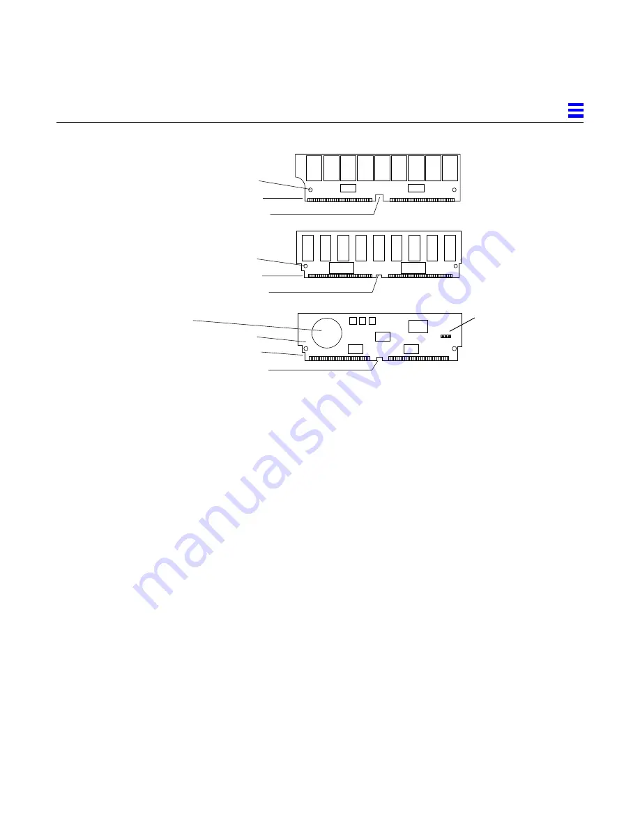
Figure 2-12 SIMM Types

2.6.1 Removal

If a SIMM or NVSIMM fails, the power-on self test (POST) will identify the
location number (also known as the U-number or J-number) of the failing
device. The socket number (J-number) is printed on the back of the board.

When replacing faulty SIMMs, refer to the location-numbers listed below.

1. Locate a faulty SIMM by matching the location number noted in the

POST message.

2. Orient the system board so that the XDBus™ connectors face you.

3. Unlock the SIMM by pressing the locking tabs toward the sides of the

socket and then tilting the SIMM forward, as shown in Figure 2-14.

4. For most SIMM sockets, there is very little space for movement, so unlock

two more SIMMs in front of the first SIMM, as shown in Figure 2-15.
This allows the faulty SIMM to tilt forward far enough to disengage the
locking pins.

5. Remove the SIMM from the socket and place it in an antistatic bag.

1

34

35

68

1

34

35

68

Type A

Type B

Alignment notch, bottom

Alignment hole (1 of 2)

Alignment notch, large

Alignment notch, bottom

Alignment hole (1 of 2)

Alignment notch, large

1

34

35

68

Battery

Type C
(NVSIMM)

Alignment notch, bottom

Alignment hole (1 of 2)

Alignment notch, large

Jumper

Содержание SPARCcenter 2000

Страница 1: ...SPARCcenter2000SystemBoardManual Part No 800 6993 13 Revision A October 1994 Sun Microsystems Computer Corporation 2550 Garcia Avenue Mountain View CA 94043 U S A ...

Страница 2: ...Inc All other product names mentioned herein are the trademarks of their respective owners All SPARC trademarks including the SCD Compliant Logo are trademarks or registered trademarks of SPARC International Inc SPARCstation SPARCserver SPARCengine SPARCstorage SPARCware SPARCcenter SPARCclassic SPARCcluster SPARCdesign SPARC811 SPARCprinter UltraSPARC microSPARC SPARCworks and SPARCompiler are li...

Страница 3: ...stem Board Description 1 2 1 3 1 System Master Board 1 3 1 4 Replacement Parts 1 3 2 Removing and Replacing System Boards and Assemblies 2 1 2 1 Halting the System 2 1 2 2 Removing a System Board 2 2 2 3 Using Standoffs 2 3 2 4 SuperSPARC Modules 2 4 2 4 1 Removal 2 5 2 4 2 Installation or Replacement 2 5 2 5 SBus Cards 2 6 ...

Страница 4: ...oval 2 19 2 8 2 Replacement 2 19 2 9 Installing the System Board 2 19 2 10 Replacing the Rear Screen 2 20 2 11 Restarting the System 2 20 2 12 Selecting a System Master 2 21 2 12 1 When a Terminal Is Present 2 21 2 12 2 When a Terminal Is Not Present 2 22 A Jumpers A 1 A 1 NVSIMM Jumpers A 1 A 2 DSBE S Link Integrity Test Jumper A 2 A 2 1 FSBE S Link Integrity Test Jumper A 3 A 3 System Board Jump...

Страница 5: ...Master Board D 1 D 1 1 Identifying the System Master D 2 D 1 2 Minimum Requirements for the System Master D 2 D 1 3 Selecting the System Master Board D 3 D 2 System Slave Boards D 5 D 3 Selecting a SuperSPARC Module Location D 5 D 4 Selecting an SBus Module Location D 6 D 5 Selecting SIMM or NVSIMM Locations D 8 D 6 SIMM or NVSIMM Installation Rules D 8 D 7 Identifying SIMM or NVSIMM Types D 9 D 8...

Страница 6: ...vi SPARCcenter 2000 System Board Manual October 1994 D 12 Connecting Ethernet D 11 D 13 Connecting Video Cables D 11 Index Index 1 ...

Страница 7: ...offs 2 4 Figure 2 4 SuperSPARC Modules A and B 2 5 Figure 2 5 SBus Slot Locations 2 6 Figure 2 6 Removing or Installing an SBus Card 2 7 Figure 2 7 SBus Card Retainer 2 8 Figure 2 8 SBus Card Rear Panel with Adapter 2 8 Figure 2 9 DSBE S SBus Card 2 10 Figure 2 10 FSBE S SBus Card 2 10 Figure 2 11 Disabling and Enabling the Link Integrity Test 2 11 Figure 2 12 SIMM Types 2 13 Figure 2 13 SIMM Loca...

Страница 8: ... A 2 Figure A 3 FSBE S SBus Card Jumper A 3 Figure A 4 Jumper Locations on the System Board A 4 Figure B 1 End and Side Views of the System Board B 2 Figure B 2 Keyboard Mouse Connector DIN 8 Pinout B 2 Figure B 3 Serial Port A and B Connector Pinouts B 3 Figure B 4 Location of XDBus Connector 0 B 8 Figure D 1 Open Boot PROM Location D 4 Figure D 2 SuperSPARC Module Locations D 6 Figure D 3 SBus C...

Страница 9: ... 3 SBus Connector 2 Connector J5702 B 6 Table B 4 SBus Connector 3 Connector J5703 B 7 Table B 5 XDBus Connector 0 Connector P0200 B 8 Table B 6 XDBus Connector 1 Connector P0300 B 11 Table B 7 SuperSPARC Module Connectors J2800 and J3100 B 13 Table C 1 Temperature Limits C 1 Table C 2 Humidity Limits C 2 Table C 3 Altitude Limits C 2 Table D 1 Example of Connector and Slot Priorities D 6 Table D ...

Страница 10: ...x SPARCcenter 2000 System Board Manual October 1994 Table D 3 Example of SBus Card Distribution D 7 Table D 4 Example of ID Numbering in a SCSI Tray D 11 ...

Страница 11: ...ware commands or procedures Refer to the operating system documentation when you need help with commands or procedures such as Shutting down the system Booting the system Configuring devices Other software procedures Depending on the operating system you are using complete descriptions of commands and procedures can be found in On line AnswerBook documentation that comes with Solaris Other softwar...

Страница 12: ...assword AaBbCc123 Command line placeholder replace with a real name or value To delete a file type rm filename AaBbCc123 Book titles new words or terms or words to be emphasized Read Chapter 6 in User s Guide These are called class options You must be root to do this Code samples are included in boxes and may display the following UNIX C shell prompt system UNIX Bourne and Korn shell prompt system...

Страница 13: ...covers to access this equipment must observe all safety precautions and ensure compliance with skill level requirements certification and all applicable local and national laws Procedures contained in this document must be performed by qualified service trained maintenance providers Note Before you begin carefully read each of the procedures in this manual If you have not performed similar operati...

Страница 14: ...xiv SPARCcenter 2000 System Board Manual October 1994 ...

Страница 15: ...on tool 1 2 Safety Precautions Caution When working on the system board use an antistatic mat which has at least 0 25 6 mm of cushioning This cushioning will protect underside components and prevent harmful board flexing Caution When the system power is turned off the AC power cord must remain plugged in to ensure a proper ground Protect yourself and the equipment by observing the following precau...

Страница 16: ... antistatic bags Breakage Parts on a board may break if the board is flexed Keep the board vertical when out of the card cage Place the board on a cushioned mat for service Springfingers Personal injury Springfingers have sharp edges so handle springfinger equipped screens and boards carefully RFI leakage The screens and panels used on the cabinet suppress radio frequency interference RFI and are ...

Страница 17: ...o Section D 1 System Master Board 1 4 Replacement Parts Table 1 2 lists part numbers for replacements Replaceable parts are shown with dotted outlines in Figure 1 2 which shows their relative locations on the board These items include SuperSPARC modules SIMMs SBus cards the OpenBoot PROM and the system board itself System error messages may specify non replaceable components by part name but these...

Страница 18: ...bits 100ns May be marked MH1M72A MH1M72BJ 8 ZA3080 etch or Z124SUN72 501 1817 xx 32 Mbyte SIMM 32Mx9 bits 100ns May be marked MH4M72J 8 Za3085 in etch or Z496SUN72 501 2196 xx NVSIMM 1Mx9 bits The SIMM may be marked MH12872SN 70H 501 2197 xx Filler panel SBus slot cutout Note screw size is M2 5 for SBus cards 340 2305 xx Filler panel card cage board slot 540 2114 xx See your Sun representative for...

Страница 19: ...us 3 SBus I F SBI I O cache IOC I O cache IOC Mem ctrl MQH Mem ctrl MQH Bus watcher BW BIC BARB Bus watcher BW BIC BARB Bus watcher BW Bus watcher BW SIMMs SIMMs SPARC B module SPARC A module Boot bus EPROM UARTs SRAM LEDS JTAG ctrl TODC NVRAM XBus XBus XBus XDBuses SuperSPARC module A SuperSPARC module B ...

Страница 20: ...1 6 SPARCcenter 2000 System Board Manual October 1994 1 ...

Страница 21: ... halt the system safely 1 Back up the system files and data if necessary 2 Halt the system using the appropriate commands 3 Wait for the system halted message and the boot monitor prompt 4 Turn the key switch on the front panel to the Standby position 5 Turn the AC power switch on the system back panel off Caution The system chassis power must be turned off and the AC power cord must remain plugge...

Страница 22: ...em board 1 Take off the rear screen by removing two Phillips screws seeFigure 2 1 Grasp the rear screen carefully the springfingers on the inner side of the rear screen have sharp edges Figure 2 1 Rear Screen 2 Disconnect and set aside any cables connected to the board backpanel Label the cables for ease of reconnection later 3 Remove the two screws that secure the board to the card cage ...

Страница 23: ...rd out of the card cage 6 Place the board on a cushioned ESD mat or in an antistatic bag Figure 2 2 System Board Ejector injector Levers in the Unlocked Position 2 3 Using Standoffs Standoffs support and secure the SuperSPARC modules and SBus cards to the system board To unlock a standoff pull up the tip Refer to Figure 2 3 To lock a standoff first ensure that the module or card rests on the stand...

Страница 24: ...perSPARC Modules The system board can have zero one or two modules Refer to Figure 2 4 If you are adding SuperSPARC modules to a system fill all A slots first before filling the B slots Start with the lowest numbered system boards Unlocked Locked Standoff SBus card or SuperSPARC module Tip Flange Standoff ...

Страница 25: ...ndoff to unlock it Refer to Figure 2 3 2 Hold the module by the edges near the connector and carefully rock the module back and forth to loosen the connector from the socket Caution The connector housing may break if the module is tilted too far 3 Place the module in an antistatic bag 2 4 2 Installation or Replacement 1 Unlock the four standoffs for this slot if they are not already unlocked Pull ...

Страница 26: ...m the side opposite from the connector press each corner of the module until the corner is seated on the flange of each standoff 6 Press down on the tip of each standoff to lock the module in place 2 5 SBus Cards Figure 2 5 shows the SBus slots on a board Figure 2 5 SBus Slot Locations For help in selecting a location for a new SBus card see Section D 4 Selecting an SBus Module Location 2 5 1 Remo...

Страница 27: ... out of the back panel opening and under the springfingers Refer to Figure 2 6 Figure 2 6 Removing or Installing an SBus Card 5 Place the SBus card in an antistatic bag 6 If a replacement card is not available install a filler panel P N 340 2305 on the back panel opening of the system board Secure the panel with the screws that were removed in step 1 Caution Ensure the panel is right side up If th...

Страница 28: ...t to remove it from the card The retainer is not needed for this installation Figure 2 7 SBus Card Retainer 2 Remove the adapter bracket from the SBus card rear panel Refer to Figure 2 8 Using a 0 Phillips screwdriver remove two screws securing the adapter to the card rear panel The adapter bracket and screws are not needed for this installation Figure 2 8 SBus Card Rear Panel with Adapter Card re...

Страница 29: ...0302 for link integrity test functionality Refer to DSBE S Figure 2 9 FSBE S Figure 2 10 a Put the shunt over both pins to disable the Link Integrity Test as shown in Figure 2 11 Disabled b Put the shunt in one pin to enable the Link Integrity Test as shown in Figure 2 11 Enabled Caution If the customer chooses to disable the test it must be disabled both at the hub and at the SBus card In the eve...

Страница 30: ...2 10 SPARCcenter 2000 System Board Manual October 1994 2 Figure 2 9 DSBE S SBus Card Figure 2 10 FSBE S SBus Card Back panel Springfinger Jackscrews Phillips screw Jumper J0302 J0302 ...

Страница 31: ...4 Guide the SBus card face plate under the springfingers and against the rear face of the back panel Refer back to Figure 2 6 The I O connectors of the card should be visible through opening in the back panel 5 Hold the card by the edges nearest the SBus connector and rest the card lightly on the two standoffs 6 Firmly but gently press the card straight down until the connector is fully seated At ...

Страница 32: ...turer so do not rely on physical appearances To verify the suitability of a replacement module refer to Table 2 1 and Figure 2 12 Table 2 1 SIMM Variations Capacity Type Markings Part Number Outline in Figure 2 12 8 Mbyte 20 pin DRAMs The SIMM may be variously marked MH1M72A MH1M72BJ 8 ZA3080 in etch or Z124SUN72 501 1817 A or B 32 Mbyte 24 pin DRAMs The SIMM may be variously marked MH4M72J 8 Za30...

Страница 33: ... face you 3 Unlock the SIMM by pressing the locking tabs toward the sides of the socket and then tilting the SIMM forward as shown in Figure 2 14 4 For most SIMM sockets there is very little space for movement so unlock two more SIMMs in front of the first SIMM as shown in Figure 2 15 This allows the faulty SIMM to tilt forward far enough to disengage the locking pins 5 Remove the SIMM from the so...

Страница 34: ...ion Numbers Figure 2 14 Unlocking a SIMM SIMM sockets XDBus connector 1 XDBus connector 0 U 3 9 0 0 U 4 3 0 0 U 3 7 0 0 U 4 1 0 0 U 3 8 0 0 U 4 2 0 0 U 3 6 0 0 U 4 0 0 0 U 4 7 0 0 U 5 1 0 0 U 4 5 0 0 U 4 9 0 0 U 4 6 0 0 U 5 0 0 0 U 4 4 0 0 U 4 8 0 0 Locking tab 1 of 2 Locking pin ...

Страница 35: ...istatic package 3 For NVSIMM only if the battery is not already activated move the jumper to the ON position as shown in Figure 2 16 If the jumper is already in the On position do not move it Caution Never move the jumper after the battery has been turned on or data contained in the NVSIMM will be lost Note It is not necessary to move jumpers on NVSIMMs that have been factory installed in a new sy...

Страница 36: ... SIMM upright to lock it in place The locking tabs should automatically lock around the SIMM Note The SIMM should require very little insertion force If there are difficulties or if the SIMM does not resemble the original SIMM the replacement SIMM may be backward check again that the alignment holes and the alignment notch align exactly with corresponding parts of the SIMM socket 7 Lock back into ...

Страница 37: ...0 2 Use an IC extraction tool to remove the PROMs 3 Place PROMs on antistatic foam plastic and store in an antistatic package 2 7 2 Replacement 1 Verify the correct PROM location Correlate the part number on each PROM to the corresponding U number as shown in Figure 2 17 Pin 1 for all sockets U1206 U1204 U1201 U1200 It may necessary to remove an SBus card from SBus slot 0 ...

Страница 38: ... 3 Check for bent pins then press firmly to seat the PROM in the socket Caution Use a cushioned ESD mat to prevent breakage of parts on the underside of the board 4 Install the remaining PROMs in the same manner 5 Install any SBus card that was removed for this procedure 2 8 TOD NVRAM Refer to Figure 2 18 for the location of the TOD NVRAM IC Figure 2 18 TOD NVRAM Location U1202 Pin 1 ...

Страница 39: ...s procedure 2 9 Installing the System Board Note For help in selecting a card cage slot for a new system board refer to Appendix D General Rules for System Configuration 1 Carefully insert the board in the proper slot in the card cage ensuring that the board does not slip out of the upper and lower card guides The component side of the board is to the right Caution Do not force the board into the ...

Страница 40: ...the System To verify that the hardware has been installed properly run the POST program 1 Turn on power to the monitor If the system lacks a monitor connect an TTY terminal to serial port A on the system master board and configure the terminal software Refer to the instruction manual shipped with the terminal for configuration instructions The most commonly used set up is 9600 bps 1 stop bit 8 dat...

Страница 41: ...oard If the NVRAM on the system master is replaced If two or more system master boards are in the card cage A specific configuration and card cage slot position is required for the system master Refer to Section D 1 System Master Board 2 12 1 When a Terminal Is Present If the terminal is connected to the correct system board watch for one board with flashing LEDs during boot up the OBP prompt will...

Страница 42: ...Present If only one system board is installed OBP automatically selects this board as the new system master If there is no terminal on the system remove all system boards except one from card cage slot 0 to force OBP to select this board as the new master ttya initialized Need to select system master from the following boards Board 0 nvram slave Prom Version nnnnnnnnn Board 1 nvram slave Prom Vers...

Страница 43: ...SIMMs DSBE S and FSBE S SBus cards and system boards A 1 NVSIMM Jumpers Before installing NVSIMMs activate the battery Move the jumper to the battery ON position Refer to Figure A 1 Figure A 1 NVSIMM Jumper Locations 1 34 35 68 Battery Battery On Battery OFF Jumper ...

Страница 44: ...h the Link Integrity Test enabled Note If the customer chooses to disable the test it should be disabled both at the hub and at the DSBE S card In the event of loss of carrier or not responding problems check the status of the link enable on both the DSBE S SBus card and the hub Figure A 2 DSBE S SBus Card Jumper To configure the Link Integrity Test jumper Put the shunt over both pins on the jumpe...

Страница 45: ... the test it should be disabled both at the hub and at the FSBE S card In the event of loss of carrier or not responding problems check the status of the link enable on both the FSBE S SBus card and the hub Figure A 3 FSBE S SBus Card Jumper To configure the Link Integrity Test jumper Put the shunt over both pins on the jumper to disable the test Put the shunt over only one pin of the jumper to en...

Страница 46: ... by a square solder pad Figure A 4 Jumper Locations on the System Board Table A 1 System Board Jumpers Label Jumper Default Setting Function J1400 Pins 2 3 In Connects 12V to RS232 line driver Pin 1 ground pin 2 line driver input pin 3 12V supply J1401 Pins 2 3 In Connects 12V to RS232 line driver Pin 1 ground pin 2 line driver input pin 3 12V supply J1501 2 3 In Pins 1 and 2 are for factory or se...

Страница 47: ...DBus connectors 0 and 1 SuperSPARC module slots A and B B 1 Connector Locations Figure B 1 shows the end view and the side view of the system board The end panel has cable connectors for serial ports and a keyboard mouse cable The side of the board has connectors for SBus cards SuperSPARC modules and the XDBus connectors These connectors are described in this appendix ...

Страница 48: ...yboard Mouse Connector DIN 8 Pinout XDBus connector 1 SBus slot 0 Diagnostic LEDs RS232 connector A Keyboard and mouse connector RS232 connector B SBus slot 1 SBus slot 2 SBus slot 3 End view Side view 0 1 2 3 BAR CODE A B Super SPARC module A XDBus connector 0 SIMM banks 0 and 1 Super SPARC module B 1 2 3 4 5 6 7 8 GND GND VCC VCC GND TDKBD GND RDKBRD ...

Страница 49: ... 14 15 16 17 18 19 20 21 22 23 24 25 1 2 3 4 5 6 7 8 9 10 11 12 13 14 15 16 17 18 19 20 21 22 23 24 25 1 2 TXDA 3 RXDA 4 RTSA 5 CTSA 6 DSRA 7 Ground 8 DCDA 9 10 11 12 13 14 DBA 15 16 DDA 17 18 19 DTRA 20 21 22 23 DAA 24 25 1 2 TXDB 3 RXDB 4 RTSB 5 CTSB 6 DSRB 7 Ground 8 DCDB 9 10 11 12 13 14 DBB 15 16 DDB 17 18 19 DTRB 20 21 22 23 DAB 24 25 Serial Port Connector A End view ...

Страница 50: ...SB_Rd 12 SBIntR_L 2 44 SB_Ack 2 76 GND 13 SB_D 12 45 SB_PA 24 77 SB_PA 1 14 SB_D 13 46 SB_PA 26 78 SB_PA 3 15 SB_D 16 47 SB_DPar 79 SB_PA 5 16 SBIntR_L 3 48 FS_VBB 80 VCC 17 SB_D 19 49 SB_Clk 0 81 SB_PA 7 18 SB_D 21 50 SB_SBG_L 0 82 SB_PA 9 19 SB_D 23 51 SB_A _L 83 SB_PA 11 20 SBIntR_L 4 52 GND 84 GND 21 SB_D 25 53 SB_D 1 85 SB_PA 13 22 SB_D 27 54 SB_D 3 86 SB_PA 15 23 SB_D 29 55 SB_D 5 87 SB_PA 1...

Страница 51: ...k 2 76 GND 13 SB_D 12 45 SB_PA 24 77 SB_PA 1 14 SB_D 13 46 SB_PA 26 78 SB_PA 3 15 SB_D 16 47 SB_DPar 79 SB_PA 5 16 SBIntR_L 10 48 FS_VBB 80 VCC 17 SB_D 19 49 SB_Clk 1 81 SB_PA 7 18 SB_D 21 50 SB_SBG_L 0 82 SB_PA 9 19 SB_D 23 51 SB_A _L 83 SB_PA 11 20 SBIntR_L 11 52 GND 84 GND 21 SB_D 25 53 SB_D 1 85 SB_PA 13 22 SB_D 27 54 SB_D 3 86 SB_PA 15 23 SB_D 29 55 SB_D 5 87 SB_PA 17 24 SBIntR_L 12 56 VCC 88...

Страница 52: ...ntR_L 16 44 SB_Ack 2 76 GND 13 SB_D 12 45 SB_PA 24 77 SB_PA 1 14 SB_D 13 46 SB_PA 26 78 SB_PA 3 15 SB_D 16 47 SB_DPar 79 SB_PA 5 16 SBIntR_L 17 48 FS_VBB 80 VCC 17 SB_D 19 49 SB_Clk 2 81 SB_PA 7 18 SB_D 21 50 SB_SBG_L 2 82 SB_PA 9 19 SB_D 23 51 SB_A _L 83 SB_PA 11 20 SBIntR_L 18 52 GND 84 GND 21 SB_D 25 53 SB_D 1 85 SB_PA 13 22 SB_D 27 54 SB_D 3 86 SB_PA 15 23 SB_D 29 55 SB_D 5 87 SB_PA 17 24 SBIn...

Страница 53: ...Ack 2 76 GND 13 SB_D 12 45 SB_PA 24 77 SB_PA 1 14 SB_D 13 46 SB_PA 26 78 SB_PA 3 15 SB_D 16 47 SB_DPar 79 SB_PA 5 16 SBIntR_L 24 48 FS_VBB 80 VCC 17 SB_D 19 49 SB_Clk 3 81 SB_PA 7 18 SB_D 21 50 SB_SBG_L 3 82 SB_PA 9 19 SB_D 23 51 SB_A _L 83 SB_PA 11 20 SBIntR_L 25 52 GND 84 GND 21 SB_D 25 53 SB_D 1 85 SB_PA 13 22 SB_D 27 54 SB_D 3 86 SB_PA 15 23 SB_D 29 55 SB_D 5 87 SB_PA 17 24 SBIntR_L 26 56 VCC ...

Страница 54: ...on 1 Section 2 Section 3 Section 4 A1 VTT B1 GND C1 GND D1 SyPwrRst_L A2 GND B2 GND C2 N C D2 VCC A3 VTT B3 SYSECR C3 GND D3 N C A4 SYRST_L B4 AC_Fail C4 SYSRST_L D4 LEDGN_L A5 LEDYEL_L B5 LEDRED_L C5 DIAGMODE D5 Fan_Fail A6 N C B6 GND C6 DC_OK D6 VCC A7 VTT B7 SY0RQ_L 1 C7 GND D7 SY0RQ_L 0 A8 GND B8 SY0RQS_L C8 SY0RQ_L 2 D8 VCC A9 SyEClk B9 GND C9 SY0RQP_L D9 SY0RQO_L A10 SyEClk_L B10 GND C10 SY0...

Страница 55: ...SY0D_L 19 B26 GND C26 SY0D_L 18 D26 VCC A27 VTT B27 SY0D_L 21 C27 GND D27 SY0D_L 20 A28 SY0D_L 23 B28 GND C28 SY0D_L 22 D28 VCC A29 GND B29 SY0D_L 24 C29 GND D29 SY0DP_L 2 A30 SY0D_L 26 B30 GND C30 SY0D_L 25 D30 VCC A31 VTT B31 SY0D_L 28 C31 GND D31 SY0D_L 27 A32 SY0D_L 30 B32 GND C32 SY0D_L 29 D32 VCC A33 GND B33 SY0DP_L 3 C33 GND D33 SY0D_L 31 A34 N C B34 GND C34 N C D34 VCC A35 VTT B35 N C C35 ...

Страница 56: ...6 VCC A47 VTT B47 SY0D_L 49 C47 GND D47 SY0D_L 48 A48 SY0D_L 51 B48 GND C48 SY0D_L 50 D48 VCC A49 GND B49 SY0D_L 53 C49 GND D49 SY0DP_L 52 A50 SY0D_L 55 B50 GND C50 SY0D_L 54 D50 VCC A51 VTT B51 SY0D_L 56 C51 GND D51 SY0DP_L 6 A52 SY0D_L 58 B52 GND C52 SY0D_L 57 D52 VBB A53 GND B53 SY0D_L 60 C53 GND D53 SY0D_L 59 A54 SY0D_L 62 B54 GND C54 SY0D_L 61 D54 VBB A55 VTT B55 SY0DP_L 7 C55 GND D55 SY0D_L ...

Страница 57: ...D D9 SY1DP_L 1 A10 N C B10 GND C10 N C D10 VCC A11 VTT B11 N C C11 GND D11 N C A12 SY1D_L 16 B12 GND C12 SY1D_L 17 D12 VCC A13 GND B13 Sy1D_L 13 C13 GND D13 SY1D_L 19 A14 SY1D_L 20 B14 GND C14 SY1D_L 21 D14 VCC A15 VTT B15 Sy1D_L 22 C15 GND D15 SY1D_L 23 A16 SY1DP_L 2 B16 GND C16 SY1D_L 24 D16 VCC A17 GND B17 Sy1D_L 25 C17 GND D17 SY1D_L 26 A18 SY1D_L 27 B18 GND C18 SY1D_L 28 D18 VCC A19 VTT B19 S...

Страница 58: ... SY1D_L 58 A40 SY1D_L 59 B40 GND C40 SY1D_L 60 D40 VCC A41 VTT B41 Sy1D_L 61 C41 GND D41 SY1D_L 62 A42 SY1D_L 63 B42 GND C42 SY1DP_L 7 D42 VCC A43 GND B43 SY1RQ_L 1 C43 GND D43 SY1RQ_L 0 A44 SysClk_L B44 GND C44 SY1RQ_L 2 D44 VCC A45 SyClk B45 GND C45 SY1RQO_L D45 SY1RQS_L A46 GND B46 ST1GT_L C46 SY1RP_L D46 VCC A47 N C B47 ST1GTT_L C47 GND D47 SY1GTT_L 0 A48 SY1GTS_L B48 GND C48 SY1GTT_L 2 D48 VC...

Страница 59: ... 53 BootData 7 4 BootData 6 Ground 54 BootData 5 5 BootData 4 55 BtStrb_L 6 XData 0 Ground 56 XData 1 7 XData 2 57 XData 3 8 XData 4 Ground 58 XData 5 9 XData 6 59 XData 7 10 XData 8 60 XData 9 11 XData 10 61 XData 11 12 XData 12 5V 62 XData 13 13 XData 14 63 XData 15 14 XData 16 5V 64 XData 17 15 XData 18 65 XData 19 16 XData 20 5V 66 XData 21 17 XData 22 67 XData 23 18 XData 24 5V 68 XData 25 19...

Страница 60: ...V 84 XData 41 35 XData 42 85 XData 43 36 XData 44 5V 86 XData 45 37 XData 46 87 XData 47 38 XData 48 5V 88 XData 49 39 XData 50 89 XData 51 40 XData 52 90 XData 53 41 XData 54 91 XData 55 42 XData 56 Ground 92 XData 57 43 XData 58 93 XData 59 44 XData 60 Ground 94 XData 61 45 XData 62 95 XData 63 46 BootCmd 2 Ground 96 BootData 3 47 BootData 2 97 BootData 1 48 BootData 0 Ground 98 CCErr_L 49 BdRst...

Страница 61: ...ture limit of 86 F 30 C Non operating US Metric US Metric Recommended range 50 104 F 10 40 C 50 140 F 10 60 C Minimum temperature 50 F at 20 RH 10 C at 20 RH 4 F 20 C Maximum temperature 104 F at 20 RH 40 C at 20 RH 140 F 60 C Maximum gradient 27 F hr 30 RH hr 15 C hr 30 RH hr 27 F hr 30 RH hr 15 C hr 30 RH hr Dwells at extremes 8 hours 8 hours 24 hours 24 hours ...

Страница 62: ...dity 80 80 95 95 Maximum gradient 30 RH hr 27 F hr 30 RH hr 15 C hr 30 RH hr 18 F hr 30 RH hr 10 C hr Dwell at extremes 8 hours 8 hours 120 hours 120 hours Table C 3 Altitude Limits Operating Non operating US Metric US Metric Maximum altitude 10 000 ft 3 km 40 000 ft 12 km Temperature range 50 104 F 10 40 C 32 F 0 C Maximum gradient 1 5kPa min 18 F hr 1 5kPa min 10 C hr 8kPa min 18 F hr 8kPa min 1...

Страница 63: ... Connecting DSBE S cables Connecting Ethernet Connecting video cables D 1 System Master Board The system board slot numbers are marked on the card cage Install system boards from the lowest card cage slot number 0 to the highest 9 Install filler panels in all empty slots A system board must be installed in card cage slot 0 If the system has a TTY console connect it to port A of the system master A...

Страница 64: ...modules will cycle The system master must meet a set of minimum hardware requirements as described next D 1 2 Minimum Requirements for the System Master The system master must have one or two SuperSPARC modules Two green LEDs marked PA and PB denote the presence of functional SuperSPARC modules in slots A and B when lit DSBE S or DWIS S interface card in SBus slot 0 The DSBE S or DWIS S card conne...

Страница 65: ...ision level of Boot PROMs installed on the board The level is expressed by the last two digits in the part number as in 525 xxxx yy where yy conveys the dash revision level 2 Likewise examine other system boards installed or to be installed in the card cage to determine the dash revision level of PROMs on these boards 3 Identify the board to be system master If a board has a higher dash revision l...

Страница 66: ...system board the system master must be reassigned by the system For information on identifying the system master and on the schemes for selecting a new system master refer to the SPARCcenter 2000 Service Manual Appendix E D 1 3 1 Additional System Master Details If a serial interface TTY console is used it must be connect to serial port A on the system master Part Number U Position 525 1328 xx U12...

Страница 67: ... to the guidelines below These guidelines are not required by system architecture but are strongly recommended to maintain consistency between systems and to simplify service procedures Install slave boards in the lowest card cage slot numbers following the system master Installing SuperSPARC modules strictly according to the guidelines presented in Section D 3 Install SIMM devices strictly accord...

Страница 68: ...Location Each system board has four SBus slots Refer to Figure D 3 The system master is the only system board that has a minimum configuration requirement for SBus cards Refer to Table D 2 Populate all other system board SBus slots for load balance Table D 1 Example of Connector and Slot Priorities Board Slot 9 8 7 6 5 4 3 2 1 0 Board present No No No No No Yes Yes Yes Yes Yes SuperSPARC Module A ...

Страница 69: ...r Slot SBus Card Comments SBus 0 DSBE S or DWIS Interface to root disk and if DSBE S to twisted pair Ethernet Interface SBus 1 CGSIX CGSIX is present if a monitor is part of machine configuration otherwise the slot is used as general SBus connector SBus 2 Available General SBus connector SBus 3 FSBE S To SCSI box Table D 3 Example of SBus Card Distribution Board Slot Number 9 8 7 6 5 4 3 2 1 0 Boa...

Страница 70: ... four groups of four slots each and two groups 0 and 1 are attached to each bus SBus slot 1 D D SBus slot 2 SBus slot 3 F F Table D 3 Example of SBus Card Distribution Board Slot Number 9 8 7 6 5 4 3 2 1 0 Group 0 of XDBus 1 Group 1 of XDBus 1 SIMM sockets XDBus connector 1 XDBus connector 0 U 3 9 0 0 U 4 3 0 0 U 3 7 0 0 U 4 1 0 0 U 3 8 0 0 U 4 2 0 0 U 3 U 4 7 0 0 U 5 1 0 0 U 4 5 0 0 U 4 9 0 0 U 4...

Страница 71: ...oth groups must be on the same board to avoid confusion it is best to put both groups on the same board Install SIMMs in both group 0 locations on every board in groups of two or four boards before adding SIMMs to any group 1 location A minor exception to the above rule is that to optimize memory performance you should keep the numbers of memory groups balanced across multiples of two or four boar...

Страница 72: ...the 8 Mbyte and 32 SIMM capacities by the number of pins on each DRAM DRAMs on 8 Mbyte SIMMs have 20 pins DRAMs on 32 Mbyte SIMMs have 24 pins The 1 Mbyte NVSIMM is identified by the presence of a battery Refer to Type C in Figure D 5 Figure D 5 SIMM Variations D 8 Locating a Disk Drive Tray The system cabinet can hold up to three disk drive trays Install the trays from the bottom up For identific...

Страница 73: ...erminates at the card cage bottom near the cabinet rear One harness connector must connect to the FSBE S card in SBus slot 3 of the master system Install a SCSI terminator on the second harness connector D 11 Connecting DSBE S or DWIS Cables Disk tray 1 in the main cabinet should be connected to the DSBE S or DWIS card in SBus slot 0 on the system master board Disk tray 1 usually contains the root...

Страница 74: ...e DSBE S FSBE S or QED S card The SPARCcenter 2000 system supports only 10Base T twisted pair Ethernet D 13 Connecting Video Cables A maximum of one CG6 color frame buffer is allowed per system It must be installed in SBus slot 1 of the system master board The color monitor keyboard must be plugged into the keyboard connector of the system master ...

Страница 75: ...D 11 connector pinout keyboard and mouse B 2 SBus slots B 4 serial ports A and B B 3 SuperSPARC module B 13 XDBus backplane B 8 D disable Link Integrity Test 2 9 disk drive tray cabling D 11 DSBE S card cabling D 11 preparing 2 9 DWIS S card cabling D 11 preparing 2 9 E enable Link Integrity Test 2 9 environmental specifications C 1 Ethernet 10Base T D 11 cabling D 11 expansion cabinet disk tray i...

Страница 76: ...place 2 16 to 2 18 operating limits C 1 to C 2 P part numbers replacement 1 4 personal safety 1 2 pinout keyboard and mouse connector B 2 SBus slot connectors B 4 serial ports A and B B 3 SuperSPARC modules B 13 XDBus backplane B 8 precautions safety 1 2 R rear screen remove 2 2 replace 2 20 replacement parts locations 1 5 part numbers 1 3 restart the system 2 20 S safety precautions 1 1 SBus card...

Страница 77: ...stallation 2 19 jumpers A 4 master 1 3 D 1 removal 2 2 replacement parts 1 3 system restart 2 20 T temperature limits environmental C 1 TOD See NVRAM tool list 1 1 TTY terminal set up 2 20 U unlock standoff 2 3 U number SIMM 2 13 V video cabling D 11 X XDBus backplane connectors B 8 ...

Страница 78: ...Index 4 SPARCcenter 2000 System Board Manual AOctober 1994 ...

Страница 79: ...RevisionHistory Revision Dash Date Comments 800 6993 13 A October 1994 Included SPARC module warning 800 6993 11 A May 1993 800 6993 10 A December 1992 First customer shipment ...

Страница 80: ...SPARCcenter 2000 System Board Manual October 1994 ...

Страница 81: ...Disagree Applicable Comments The information provided in SPARCcenter 2000 System Board Manual was complete Strongly Strongly Not Agree Agree Disagree Disagree Applicable Comments The information I needed was easy to find Strongly Strongly Not Agree Agree Disagree Disagree Applicable Comments The manual was useful to me Strongly Strongly Not Agree Agree Disagree Disagree Applicable Comments Do you ...

Страница 82: ...LED IN THE UNITED STATES SUN MICROSYSTEMS INC Attn Manager Hardware Publications MS MTV15 42 2550 Garcia Avenue Mt View CA 94043 BUSINESS REPLY MAIL FIRST CLASS MAIL PERMIT NO 1 MOUNTAIN VIEW CA POSTAGE WILL BE PAID BY ADDRESSEE ...

Отзывы: