


11
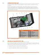
COMPONENT DESCRIPTION
3.3
COMPRESSOR COOLING
The compressor cooling and lubrication system is designed to provide adequate lubrication as well as
maintain the proper operating temperature of the compressor.
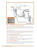
The Fan (
16
) vents the heat coming from the compression of the air with the oil, which flows through the
Cooler (
4
) and cooled due to the air issued from the Fan. (
16
)
When operating, the compressor fluid circulates from the Separator (
6
) to the Cooler (
4
). This circulation is
caused by the pressure difference between the Separator (
6
) high pressure and the low pressure zone of the
Air End (
7
) compressor unit. The fluid is then returned to the main Oil Filter (
2
) where it is filtered prior to
re-injection into the compression chamber and bearings of the compressor unit.
3.4
SEPARATOR
The separator has four main functions:
1.
Primary fluid separation system
2.
Final fluid separation system
3.
Fluid tank
4.
Air reserve for the regulation
The compressed air/fluid mixture is then pushed into the separator, where it flows through the separator
body. This change of direction slows down the air speed and creates larger droplets of fluid which fall to the
bottom of the sump. The remaining oil contained in the air is separated in the separator cartridge and via
gravity travels down to the sump where it is pushed by pressure difference in the dip tube that leads back to
the air end suction. The separator is EC certified.
A calibrated port, located downstream from the separator, helps maintain a minimum receiver pressure of 51
psig (3.5 bar) under all conditions. This pressure is necessary for proper air/fluid separation and proper fluid
circulation. A Pressure Relief Valve (
15
) located on the separator is set to open if the sump pressure exceeds
145 psig (10 bar).
3.5
COMPRESSOR FLUID
The compressor fluid (oil) has three main functions:
1.
As a coolant it controls the rise of air temperature associated with the heat of compression;
2.
It seals the leakage paths between the rotor and the stator, and also between the rotors themselves;
3.
It acts as a lubricating film between the rotors allowing one rotor to directly drive the other, which is an
idler.
3.6
CAPACITY CONTROL SYSTEM
The control system is designed to match air supply to air demand and to prevent excessive discharge
pressure when the compressor is operating but air is not being used. Control of air delivery is accomplished
both by inlet valve regulation and engine speed control as directed by the adjustable discharge pressure
regulator valve(s). The following information explains the operation of the control from a condition of “no
load” to a condition of “full capacity” at working pressure.
For the working pressure range of your machine, refer to applicable data in the specifications section. The
inlet valve cylinder pressure chamber is pneumatically connected to the dry side of the receiver via the
pressure regulator valve. When the separator pressure is below the set point of the regulator valve no
pressure will exist in the inlet valve cylinder. Under these conditions, the inlet valve will remain wide open,
causing the compressor to deliver full capacity. As the demand for air decreases, the receiver pressure
will rise, and when this pressure level exceeds the set point of the pressure regulator valve, control signal
pressure will be allowed to enter the inlet valve chamber which in turn will move the modulating piston and
the valve plate to a closed condition, thereby throttling the incoming air. A separate throttle air cylinder
controls engine speed.
The air cylinder is spring loaded in the full speed position when there is no air signal from the pressure
regulator valve. Whenever less than full capacity is required, receiver pressure increases, thereby opening
the pressure regulator, which allows a pressure signal to enter the throttle air cylinder and reduce the engine
speed until it matches the air requirements from 100% down to 60%. From 60% down to 0% both engine
speed reduction and inlet valve modulation act together to reduce air output.
Содержание D110PKU
Страница 4: ......
Страница 6: ...vi About This Manual ...
Страница 13: ...5 2 SPECIFICATIONS TOPICS IN THIS SECTION Technical Data 6 Dimensions 7 ...
Страница 16: ...8 Specifications ...
Страница 44: ...36 Troubleshooting ...
Страница 48: ...40 Parts Catalog 8 6 ENGINE ASSEMBLY ...
Страница 50: ...42 Parts Catalog 8 7 ENGINE MOUNTING ASSEMBLY ...
Страница 52: ...44 Parts Catalog 8 8 ENGINE TO FRAME ASSEMBLY ...
Страница 54: ...46 Parts Catalog 8 9 BATTERY ASSEMBLY ...
Страница 56: ...48 Parts Catalog 8 10 EXHAUST ASSEMBLY ...
Страница 58: ...50 Parts Catalog 8 11 COMPRESSOR ASSEMBLY ...
Страница 60: ...52 Parts Catalog 8 12 INLET VALVE ASSEMBLY ...
Страница 62: ...54 Parts Catalog 8 13 AIR FILTER ASSEMBLY ...
Страница 64: ...56 Parts Catalog 8 14 RECEIVER ASSEMBLY ...
Страница 66: ...58 Parts Catalog 8 15 RECEIVER ASSEMBLY TO FRAME ...
Страница 68: ...60 Parts Catalog 8 16 CONTROL TUBING ASSEMBLY ...
Страница 70: ...62 Parts Catalog 8 17 COOLING ASSEMBLY ...
Страница 72: ...64 Parts Catalog 8 18 COOLING ASSEMBLY ATTACHMENT TO FRAME ...
Страница 74: ...66 Parts Catalog 8 19 COOLING SYSTEM HOSES AND RECOVERY TANK INSTALLATION ...
Страница 76: ...68 Parts Catalog 8 20 OIL FILTER AND DISCHARGE HOSE ASSEMBLY ...
Страница 78: ...70 Parts Catalog 8 21 FUEL TANK ASSEMBLY ...
Страница 80: ...72 Parts Catalog 8 22 INSTRUMENT PANEL ASSEMBLY ...
Страница 82: ...74 Parts Catalog 8 23 CANOPY ASSEMBLY ...
Страница 84: ...76 Parts Catalog 8 24 CANOPY INSTALLATION ...
Страница 86: ...78 Parts Catalog 8 25 LIFTING BAIL ASSEMBLY ...
Страница 88: ...80 Parts Catalog 8 26 FRONT CROSSMEMBER ASSEMBLY ...
Страница 90: ...82 Parts Catalog 8 27 LIGHT PACKAGE ...
Страница 92: ...84 Parts Catalog 8 28 FENDER INSTALLATION ...
Страница 94: ...86 Parts Catalog 8 29 AXLE AND WHEEL ASSEMBLY ...
Страница 98: ...NOTES ...
Страница 99: ...NOTES ...