background image

76

Code: 02250144

--

517 SRV

--

250 --- SRV

--

2400

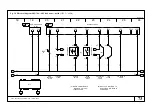
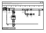
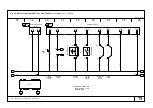
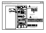
Fig. 10 Electrical diagram SRV

--

700 --- SRV

--

800 water---cooled

(460V 3~ 60Hz)

to page 78

0

1

2

3

4

5

6

7

8

460V 3~ 60Hz

QF I

n

n=0.03A

RECOMMENDED

0V

460V

0V

460V

LI

MI

T

O

F

E

Q

U

IP

ME

NT

MC1

d

d

d

(0.5A T)

(20A)

QF1

A2

QS

L3

L3

L2

L2

R1

S1

R1

S1

FU2

R4

S4

L1

L1

T1

FU1

18

18

0V

8

FU6

(2A F)

50

50VA

TC2

24V

7

0V

6

230V 1

(500mA T)

FU5

(2A F)

51

(500mA T)

FU4

0

2

100VA

TC1

FU3

0

9

2

9

(0.5A T)

ELECTRICAL SUPPLY LINE

3  EARTH (GND)

3 GND 12AWG

3

2

2

0

0

MAIN

DISCONNECTOR

SWITCH

COMPRESSOR MOTOR

AUXILIARY

TRANSFORMER

FUSES

AUXILIARY

TRANSFORMER

AUXILIARY

FUSES

INVERTER

U

V

W

U/T1 V/T2 W/T3

L3

L2

L1

see page 80

2

O1

5

L

O

H

3

4

L FM

P24

1

CM2 12 11

U0 V0 W0

0

0

0

0

0

0

1

1

1

L1

S2

R2

T2

Содержание SRV-1000

Страница 1: ...EN F 272713 DATE 30 09 2004 ISSUE 4 CODE 02250144 517 VALID FROM SERIAL NUMBER 2644900001 User manual Page 1 Manuale d uso Pagina 17 SRV 250 SRV 2400 refrigeration dryer 60Hz ...

Страница 2: ...ompiled to help the final user perform just those oper ations which do not require removal of the panels All other operations which involve the removal of covers from instruments or electrical circuit breakers using special tools must only be carried out by trained personnel due to the danger of rotating parts or live components Operations on the Microprocessor which are not password protected may...

Страница 3: ...ith a strong cardboard box strapped to a wooden pallet Instruction symbols UNI ISO 780 for the movement transport and stocking of the product are printed on two sides of the packing FRAGILE HANDLE WITH CARE THIS WAY UP KEEP DRY DO NOT ROLL STACKING LIMITATION USE NO HOOKS Kg max 1 3 Transport S Keep the unit in an upright position and do not leave it outdoors S Only move this machine using a forkl...

Страница 4: ... dryer inlet i For water cooled versions it is recommended to install a filter on the condenser water inlet to prevent the ingress of debris that will gradually choke thepassages with negative effects on dryer performance j Water cooled versions RECOMMENDATIONS FOR THE WATER AND ITS QUALITY The water quality should satisfy the following conditions Parameter Concentration Parameter Concentration Mi...

Страница 5: ...rrent and earth leakage circuit breaker upstream from the plant IDn 0 3A with a 0 12 inch 3 mm gap between contacts when open refer also to local laws 2 2 Condensate drain connection a The drainer is already installed and cabled b Connect the condensate drain outlet to the drainage system c Any maintenance operation must be done by an expert technician N B The dryer is supplied either with a timed...

Страница 6: ...r Avoid allowing compressed air to enter the dryer when the dryer is switched off or when it is in an alarm situation which stops the refrigeration compressor 3 4 Remote on off Remote on off is enabled or disabled by the parameter B06 and can be performed either using a remote on off switch connected to terminals 51 63 of Dryer s ter minals board or a supervisor system There are 3 settings for par...

Страница 7: ...esign OFF appears Metric Imperial data display when a temperature or a pressure is shown on thedisplay it indicates theunitsof thereading Main switch Disconnect the dryer from the mains S moves back to the previous parameter type when selecting the type of parameter to modify S moves back to the previous parameter number when selecting the parameter to modify S increases the parameter value when m...

Страница 8: ...ed can be modified hour meter parameters for instance cannot be modified the parameter value can be increased or diminished using the arrow keys When the prog key is pressed the new value set is recorded in the parameter and the display goes back to showing the type and number of parameter being edited If status report is pressed after modifying the displayed value the display goes back to showing...

Страница 9: ...o the parameters and the display will show the type of parameters selected followed by the figures 01 Now proceed as described above to choose and modify a parameter If the sequence of figures is not correct the display goes back to showing P 0 start entering the password again or press status report to give up modifying the protected para meters Every time the status report key is used to make th...

Страница 10: ...o Auto b 15 High dew point warning temperature 0 0 30 0 32 0 86 0 C F 10 0 50 0 b 16 High dew point warning delay 1 60 mins 15 b 17 High air inlet temperature warning 10 99 50 210 C F 65 0 149 0 b 18 High ambient temperature warning 0 70 32 158 C F 55 131 b 19 Low ambient temperature warning 30 30 22 86 C F 2 35 6 b 20 Alarm sound activation time 0 continuously 0 900 secs 0 b 21 Version and revisi...

Страница 11: ...ing Signal only Immediate HA High ambient temperature warning Signal only Immediate LA Low ambient temperature warning Signal only Immediate UA User alarm See par 6 3 Programmable 0 600 sec dA Condensate drain alarm Signal only Immediate PS Programmed maintenance due Warning Signal only Immediate 6 3 User alarms The Dryer is equipped with a user alarm input terminals 51 and 66 of Dryer s ter minal...

Страница 12: ...ther with dryer in standby or working The unit working hours counter at the intervention of alarm No 1 is shown Dew point temperature is shown The display showns the evaporation temperature The evaporation pressure is shown The suction temperature is shown The alarm No 1 code is shown The alarm No 2 code is shown Up to 8 alarms are stored in memory The ambient temperature is shown The air inlet am...

Страница 13: ...OR Make sure the compressor head temperature is between 59 F 15 C and MONTHLY Make sure the compressor head temperature is between 59 F 15 C and 203 F 95 C when running If this is not the case consult Chap 10 EVERY CONDENSER Remove any dust from the condenser fins COMPRESSOR EVERY 4 MONTHS COMPRESSOR Make sure compressor power consumption complies with data plate specifica tions CONDENSATE DRAIN C...

Страница 14: ... electrical cable copper PVC 7 3 Refrigerant leaks in the refrigeration circuit FOREWORD The unit is delivered in perfect working order already charged as specified in Fig 5 IFALEAKISDETECTED INTHE REFRIGERANT CIRCUIT SEEKTECHNI CAL ASSISTANCE 7 4 Refrigerant charging see Fig 5 THIS OPERATION MUST ONLY BE PERFORMED BY A REFRIGERANT SPECIALIST WHEN REPAIRING THE REFRIGERANT CIRCUIT COLLECT ALL THE ...

Страница 15: ...y valve 1 Correct settings 2 Change microprocessor 3 Change valve Yes always ON Condensing pressure too high because of 1 PV settings too high 2 Dirty condenser surface 3 Fan on multi fan units doesn t work 1 Change PV 2 Clean condenser 3 Change fan NO High dew point Hd Wrong Thermostatic valve setting excessively closed or excessively open Adjust setting Yes Thermostatic valve broken Substitute v...

Страница 16: ...ge Re charge according to name plate data NO HP switch broken Substitute HP switch NO Leakage in evaporator compressed air in refrigerant circuit Substitute evaporator NO High Pressure alarm HP Condensing pressure too high because of 1 PV settings too high 2 Dirty condenser surface 3 Fan broken 1 Substitute PV 2 Clean condenser 3 Substitute fan NO Excessive ambient temperature Decrease ambient tem...

Страница 17: ...16 Code 02250144 517 SRV 250 SRV 2400 English 16 ...

Страница 18: ...ns pouvant être réalisées lorsque les panneaux sont fermés Les opérations pour lesquelles il est nécessaire d ouvrir les couvercles d instruments ou d interrupteurs électriques à l aide d outils ne doivent être effectuées que par un personnel expert car certaines parties tournantes de la machine sont en mouvement et d autres composants sont sont tension Les opérations sur le microprocesseur qui ne...

Страница 19: ...sécheur est contenu dans une boîte en carton fixée è l aide de feuillards à une pa lette en bois Sur les côtés de chaque emballage sont estampillés les symboles UNI ISO 780 pour le transport la manutention et le stockage FRAGILE HANDLE WITH CARE THIS WAY UP KEEP DRY DO NOT ROLL STACKING LIMITATION USE NO HOOKS Kg max 1 3 Transport S Veiller à ce que l unité soit toujours en position verticale et n...

Страница 20: ...oit être près de l arrivée du sécheur i Il est recommandé pour les modèles à refroidissement liquide d installer un fil tre sur l entrée du retour d eau du condenseur afin d empêcher le dépôt de débris qui provoquerait une obstruction progressive des canalisations avec les conséquences négatives que cela peut engendrersur lesprestations del appareil j Pour les modèles à refroidissement liquide REC...

Страница 21: ...installation IDn 0 3A avecunécart de0 12 inch 3 mm entre lescontacts lorsqu il est ouvert reportez vous également à la législation locale 2 2 Raccordement purge condensats a Le purgeur est déjà installé sur la machine voir manuel à part b raccorder le tuyau d évacuation de la condensation au système de drainage c Toute opération d entretien doit être effectuée par un technicien spécialisé N B Le s...

Страница 22: ...ermettre l entrée d air comprimé dans le séchoir lorsque celui ci est éteint ou dans un état d alarme arrêtant le compresseur de réfrigération 3 4 Marche et Arrêt La marche et l arrêt de la commande à distance sont activés ou pas grâce au paramètre B06 et peuvent passer d un état à l autre en utilisant un commutateur de commande à distance relié aux bornes 51 63 de la plaque à bornes du sécheur ou...

Страница 23: ...eille le signe OFF apparaît Affichage des données métriques ou impériales lorsque la température ou la pression s affichent sur l écran ce dernier indique les unités de lecture Commutateur principal Déconnecte le sécheur de l alimentation S revient au type de paramètre précédent lors de la sélection du type de paramètre à modifier S revient auparamètreprécédent lors delasélectionduparamètreàmodifi...

Страница 24: ...est modifiable ce qui n est pas le cas par exemple du compte heures les touches fléchées permettent d augmenter ou de diminuer la valeur du paramètre En appuyant sur la touche prog la nouvelle valeur définie est enregistrée dans le paramètre et l afficheur visualise de nouveau le type et le numéro du paramètre en phase d édition Si après avoir modifié la valeur visualisée vous appuyez sur rapport ...

Страница 25: ...t le type de paramètres sélec tionné suivi des chiffres 01 procéder ensuite comme décrit ci après pour choisir et modifier un paramètre Si la séquence de chiffres n est pas correcte l afficheur visualise de nouveau P 0 recommencer la saisie du mot de passe ou appuyer sur rapport d état pour renoncer à la modification des paramètres protégés Chaque fois que l on appuie sur la touche rapport d état ...

Страница 26: ... Alarme de température élevée du point de rosée 0 0 30 0 32 0 86 0 C F 10 0 50 0 b 16 Délai de l alarme de température élevée du point de rosée 1 60 mins 15 b 17 Avertissement haute température entrée air 10 99 50 210 C F 65 0 149 0 b 18 Avertissement haute température ambiance 0 70 32 158 C F 55 131 b 19 Avertissement basse température ambiance 30 30 22 86 C F 2 35 6 b 20 Période d activation de ...

Страница 27: ...lisation Immédiat HA Avertissement de haute température ambiante Simple signalisation Immédiat LA Avertissement de basse température ambiante Simple signalisation Immédiat UA Alarme utilisateur Voir para 6 3 Programmable 0 600 sec dA Alarme du drain des condensats Simple signalisation Immédiat PS Intervalle d entretien dû Avertissement Simple signalisation Immédiat 6 3 Alarmes utilisateur Le séche...

Страница 28: ... plus récente pendant Le rapport d état est disponible quel que soit le mode du sécheur marche ou veille Le compteur des heures de travail de l unité s affiche à l intervention de l alarme No 1 La température du point de rosée est affichée L écran indique la tempéra ture d évaporation La pression d évaporation est indiquée La température d aspiration est affichée Le code d alarme No 1 est affiché ...

Страница 29: ...compresseur alors que celui ci est en marche est comprise entre environ 59 F 15 C et 203 F 75 C Dans le cas contraire consulter le CHAPITRE 10 TOUS LES CONDENSEUR Nettoyer les ailettes du condenseur afin d éliminer d é ventuels dépôts de poussière TOUS LES 4 MOIS p p COMPRESSEUR S assurer que l absorption électrique du compresseur est comprise dans la plage indiquée sur la plaque TOUS LES ANS PURG...

Страница 30: ...nseur acier cuivre aluminium réfrigérant R407C H F C vannes laiton câbles électriques cuivre PVC 7 3 Perte de réfrigérant du circuit frigorifique VORBEMERKUNG L unité arrive déjà chargée et en parfait état de marche comme le montre la Fig 5 EN CAS DE PERTE DU CIRCUIT FRIGORIFIQUE CONTACTER L ASSIS TANCE 7 4 Charge de réfrigérant voir Fig 5 CETTE OPERATION DOIT ETRE REALISEE PAR UN FRIGORISTE EXPER...

Страница 31: ...er microprocesseur 3 Changer le clapet OUI toujours sur ON Point de rosée élevée Hd Pression de condensation trop élevée à cause de 1 Valeurs du pressostat PV trop élevées 2 Surface du condensateur sale 3 Ventilateur hors service sur des unités de ventilateurs en série 1 Changer PV 2 Nettoyer le condensateur 3 Remplacer le ventilateur NON Hd Valeur incorrecte de la vanne thermostatique trop fermée...

Страница 32: ...n endommagé Changer le commutateur Haute Pression NON Fuite dans l évaporateur air comprimé dans le circuit réfrigérant Changer l évaporateur NON Alarme de pression élevée HP Pression de condensation trop élevée à cause de 1 Valeurs du pressostat PV trop élevées 2 Surface du condensateur sale 3 Ventilateur hors service 1 Changer PV 2 Nettoyer le condensateur 3 Changer le ventilateur NON Températur...

Страница 33: ...32 Code 02250144 517 SRV 250 SRV 2400 Français ...

Страница 34: ...44 517 SRV 250 SRV 2400 Fig 1 Installation to compressed air ring main recommended compressor bypass oil water separator receiver D r y e r filter max 3µm filter and optionally available ALTERNATIVE RECEIVER POSITION ...

Страница 35: ...stified only when the dryer is not in working order 3 During the unit guarantee period the Schrader valvecanbeused by authorizedstaff only otherwise any damage caused by a wrong refrigerant recharge will not be under warranty a a1 f b g Attention components under power Air inlet Air outlet Water inlet Water outlet d e d1 e1 h Condensate drain connection See Chapter 2 c max 3µm COD 109574 SRV 1400 ...

Страница 36: ...the dryer 5 minutes be fore slowly opening the air inlet valve If the airflow is to bestopped only switch the dryer off after closing the air inlet i l p WARNING Risk of electric shock can cause injury or death Disconnect all remote electric power supplies before servicing BSPP pipe threads use supplied adapters m o ATTENTION Never pass compressed air throughthedryerwhen it is stopped Always start...

Страница 37: ...36 Code 02250144 517 SRV 250 SRV 2400 Fig 3 Positioning of labels attached to the dryer SRV 250 SRV 500 air cooled o ...

Страница 38: ...37 Code 02250144 517 SRV 250 SRV 2400 Fig 3 Positioning of labels attached to the dryer SRV 700 SRV 2400 air cooled o ...

Страница 39: ...38 Code 02250144 517 SRV 250 SRV 2400 Fig 3 Positioning of labels attached to the dryer SRV 700 SRV 2400 water cooled q ...

Страница 40: ...2 17 4 670 26 4 674 26 5 170 B 91 214 8 4 1211 47 7 BASE FIXING HOLES POSITION 917 36 1 670 26 4 14 0 6 ø8 526 20 7 72 14 0 6 72 921 36 3 A 60 214 276 10 9 330 345 38 1 5 40 1 6 360 14 2 330 13 101 255 10 465 18 3 air outlet NOTE distance expressed in inches 6 7 2 4 3 6 2 8 2 8 13 13 6 4 8 4 Model A SRV 250 157 2 6 2 A SRV 325 SRV 500 179 7 1 B SRV 250 416 16 4 B SRV 325 SR 500 383 15 1 200 LEFT 1...

Страница 41: ... point CENTRE OF GRAVITY X 16 5 185 160 301 160 135 641 25 2 60 30 base fixing 4 10 0 39 holes position 16 5 7 3 6 3 11 9 6 3 2 4 1 2 5 3 0 6 0 6 NOTE distance expressed in inches 7 1 180 7 1 only for model SRV 700 SRV 1200 1370 53 9 1640 64 6 130 450 17 5 700 27 6 120 100 174 condensate drain connection 1 2 BSP F 1 2 NPT F 254 425 16 7 COOLING AIR INLET 6 8 10 4 7 5 1 3 9 10 4 3 1 Model X SRV 700...

Страница 42: ...V 2000 SRV 2400 395 15 5 503 19 8 370 160 480 160 262 1016 40 60 30 base fixing 4 10 0 39 holes position 1010 39 8 320 12 6 35 power cable inlet 36 remote control cable entry point 16 5 16 5 0 6 0 6 14 6 6 3 18 9 6 3 10 3 7 1 NOTE distance expressed in inches 2 4 1 2 1370 53 9 1640 64 6 130 450 17 5 700 27 6 120 100 174 condensate drain connection 1 2 BSP F 1 2 NPT F 254 425 16 7 COOLING AIR INLET...

Страница 43: ... air outlet FRONT SIDE REAR 180 1010 39 8 503 19 8 680 26 8 1310 51 6 320 12 6 35 power cable inlet 36 remote control cable entry point CENTRE OF GRAVITY Model X SRV 700 SRV 1200 317 12 5 X SRV 1400 350 13 8 X 16 5 185 160 301 160 135 641 25 2 60 30 base fixing 4 10 0 39 holes position 16 5 7 3 6 3 11 9 6 3 2 4 1 2 5 3 0 6 0 6 NOTE distance expressed in inches water outlet water inlet 433 17 914 3...

Страница 44: ... 350 13 8 X SRV 2000 SR 2400 395 15 5 503 19 8 370 160 480 160 262 1016 40 60 30 base fixing 4 10 0 39 holes position 14 6 6 3 18 9 6 3 10 3 7 1 1010 39 8 320 12 6 35 power cable inlet 36 remote control cable entry point 16 5 16 5 0 6 0 6 433 17 914 36 62 2 4 NOTE distance expressed in inches 2 4 1 2 1370 53 9 1500 59 130 450 17 5 700 27 6 120 100 174 condensate drain connection 1 2 BSP F 1 2 NPT ...

Страница 45: ...oz A 3lb 12oz W 11 2 A 9 9 W 8 1 A 3 4 BSP F SRV 800 418 922 4 30 A 1 75 W 9lb 8oz A 3lb 14oz W 11 7 A 10 4 W 8 1 A 6 7 W 60 C 5 C 50 C 3 NPT M 3 4 BSP F with adaptor 3 4 NPT F 12 bar SRV 1000 SRV 1200 449 990 5 00 A 2 80 W 11lb 0oz A 6lb 3oz W 9 5 A 8 3 W 60 C 140 F 5 C 41 F 50 C 122 F 3 4 NPT F 12 bar 174 PSI SRV 1400 477 1 052 7 50 A 2 40 W 16lb 9oz A 5lb 5oz W 13 0 A 11 4 W 4 ANSI 150 LBS 1 BS...

Страница 46: ...static interception electrovalve 10 air air heat exchanger 12 fan pressure switch 15 high pressure switch 18 high pressure manometer 19 thermostatic valve T0 dew point temperature sensor T1 evaporation temperature sensor T2 refrigerant suction temperature sensor T3 ambient temperature sensor T4 air inlet temperature sensor P1 low pressure transmitter MICROPROCESSOR CONTROL 9a PV 12 3 2 9 19 7 4 10...

Страница 47: ... start up by pass electrovalve 9b thermostatic interception electrovalve 10 air air heat exchanger 12 fan pressure switch 15 high pressure switch 18 high pressure manometer 19 thermostatic valve 21 distribution capillary T0 dew point temperature sensor T1 evaporation temperature sensor T2 refrigerant suction temperature sensor T3 ambient temperature sensor T4 air ilet temperature sensor P1 low pre...

Страница 48: ... thermostatic interception electrovalve 10 air air heat exchanger 15 high pressure switch 18 high pressure manometer 19 thermostatic valve 21 distribution capillary 28 pressostatic water valve T0 dew point temperature sensor T1 evaporation temperature sensor T2 refrigerant suction temperature sensor T3 ambient temperature sensor T4 air inlet temperature sensor P1 low pressure transmitter 8 9b 7 19...

Страница 49: ...600 02250129 602 9 02250144 540 9a 9b 02250144 541 12 02250129 626 14 02250144 553 15 A 02250141 114 15 W 02250139 295 18 02250129 623 19 A 02250144 527 02250144 528 02250144 529 02250144 530 19 W 02250144 528 02250148 007 02250144 530 28 02250129 632 02250129 633 02250129 634 29 02250144 542 30 z 02250144 532 02250144 533 30 L 02250144 534 02250144 532 02250144 533 02250144 535 30a 02250144 554 3...

Страница 50: ...e 10 air air heat exchanger 11 insulation 12 fan pressure switch 14 main disconnector switch 15 high pressure switch 18 low pressure manometer 19 thermostatic valve 25 thermometer sensor pocket 27 gas charge point 29 inverter cooling fan 30 inverter automatic switch 31 fan motor contactor 33 auxiliary transformer 230V 34 auxiliary transformer 24V 35 power cable inlet PG 21 4 13 18 mm 36 remote con...

Страница 51: ...er 11 insulation 12 fan pressure switch 14 main disconnector switch 15 high pressure switch 18 low pressure manometer 19 thermostatic valve 21 distribution capillary 25 thermometer sensor pocket 27 gas charge point 30 inverter automatic switch 30a fan motor automatic switch 31 fan motor contactor 33 auxiliary transformer 230V 34 auxiliary transformer 24V 35 power cable inlet PG 21 4 13 18 mm 36 re...

Страница 52: ...er 11 insulation 12 fan pressure switch 14 main disconnector switch 15 high pressure switch 18 low pressure manometer 19 thermostatic valve 21 distribution capillary 25 thermometer sensor pocket 27 gas charge point 30 inverter automatic switch 30a fan motor automatic switch 31 fan motor contactor 33 auxiliary transformer 230V 34 auxiliary transformer 24V 35 power cable inlet PG 21 4 13 18 mm 36 re...

Страница 53: ...air air heat exchanger 11 insulation 14 main disconnector switch 15 high pressure switch 18 low pressure manometer 19 thermostatic valve 21 distribution capillary 25 thermometer sensor pocket 27 gas charge point 28 pressostatic water valve 30 inverter automatic switch 33 auxiliary transformer 230V 34 auxiliary transformer 24V 35 power cable inlet PG 21 4 13 18 mm 36 remote control cable entry poin...

Страница 54: ...RV 500 12 START 261 PSIg 18 bar DIFF 58 PSIg 4 bar SRV 700 SRV 2400 Fan pressure switch PV g STOP 203 PSIg 14 bar SRV 700 SRV 2400 SRV 250 SRV 2400 High pressure switch HP 15 STOP 406 PSIg 28 bar START 275 6 PSI 19 bar reset SRV 700 SRV 2400 Water pressostatic valve 28 261 PSIg 18 bar 1 0 calibr ...

Страница 55: ...R1 S1 FU2 L1 L1 T1 FU1 KM1 A2 A1 18 18 0V 40 FU6 2A F 50 50VA TC2 24V 41 FU5 2A F 51 PV EV2 1 1 3 2 4 2 0 2 0 0 9 2 9 TK WHITE U1 BROWN V1 BLUE W1 BLACK U2 RED V2 GREY W2 ORANGE 0 5A T p P NO 3 X 3 NC 3 ELECTRICAL SUPPLY LINE 3 PHASES EARTH GND 3x14AWG GND 14AWG 3 3 51 67 TK TK MAIN DISCONNECTOR SWITCH COMPRESSOR MOTOR FAN MOTOR AUXILIARY TRANSFORMER FUSES AUXILIARY TRANSFORMER AUXILIARY FUSES INV...

Страница 56: ...0 50VA TC2 24V 41 FU5 2A F 51 0 2 PV 3 2 2 0 9 2 9 0 5A T p P NO 3 X 3 NC 3 ELECTRICAL SUPPLY LINE 3 PHASES EARTH GND 3x12AWG GND 12AWG 3 U1 V1 W1 2 4 1 3 R3 S3 6 7 KM1 5 T3 6A QF2 MAIN DISCONNECTOR SWITCH COMPRESSOR MOTOR FAN MOTOR AUXILIARY TRANSFORMER FUSES AUXILIARY TRANSFORMER AUXILIARY FUSES FAN MOTOR CONTACTOR INVERTER FAN PRESSURE SWITCH 0 GND N C L N 2 0 2 65 51 N O C 24 24 ELECTRONIC DRA...

Страница 57: ... 2 11 12 13 12 13 DIGITAL OUTPUTS J13 A1 C4 NO4 NO5 NO6 C4 A1 YV3 YV4 0 A1 J13 14 2 14 DIGITAL OUTPUTS C7 NO7 HP p NO NC X 20 X 33 C7 J15 A1 DIGITAL NO8 C8 NC8 31 32 33 J14 J15 MAX 250V Imax 1A OUTPUTS GENERAL ALARM WARNING FREE CONTACT HIGH PRESSURE ALARM RELAY BY PASS VALVE HOT GAS VALVE THERMOSTATIC EXPANSION VALVE CONDENSATE DRAIN VALVE NOT INSTALLED IF ELECTRONIC DRAIN IS FORESEEN ...

Страница 58: ...THERS 32 12 11 51 32 62 62 61 G0 ID2 J5 ID1 A1 50 50 31 51 31 ID8 65 ON BY OTHERS 51 51 A 51 51 RESET 63 63 64 64 4 4 51 51 51 66 65 66 67 67 ID3 DIGITAL INPUT ID4 ID5 ID6 ID7 50 IDC1 A REMOVE BRIDGE IF REMOTE ON OFF IS INSTALLED 51 51 51 51 51 HIGH PRESSURE ALARM INVERTER ALARM REMOTE ON OFF ALARM REMOTE RESET CONDENSATE DRAIN ALARM USER ALARM FAN THERMAL ALARM 8 8 B B REMOVE BRIDGE IF ELECTRONIC...

Страница 59: ...D B6 51 62 50 51 050 52 AL0 AL1AL2 5 H O L O1 L 4 3 12 CM2 FM 2 1 11 P24 050 51 50 52 53 Y3 VG VG0 Y2 ANALOG OUTPUTS Y1 Y4 24 22 KA1 21 10 56 54 NO2 C1 NO1 DIGITAL OUTPUTS J3 A1 J4 A1 J12 A1 NO3 C1 56 G GO J1 A1 51 50 A1 J3 J2 J4 J12 A3 J1 53 DEW POINT TEMPERATURE SENSOR EVAPORATION TEMPERATURE SENSOR REFRIGERANT TEMPERATURE SENSOR SUCTION EVAPORATION PRESSURE TRANSMITTER AMBIENT TEMPERATURE SENSO...

Страница 60: ...65V 51 W2 V2 67 0 24V 11 2 0 0 0 0 2 2 3 5 230V 12 13 14 50 51 51 50 62 24V FREE A 51 2 0 51 51 51 C B 63 64 65 66 32 31 33 24V 230V QS TC2 KM1 FU1 FU2 QF1 FU5 KA1 FU6 CONTACTS A REMOVE BRIDGE IF REMOTE ON OFF IS INSTALLED B REMOVE BRIDGE IF CONDENSATE DRAIN ALARM IS INSTALLED C REMOVE BRIDGE IF USER ALARM IS INSTALLED 1 2 3 4 5 6 1 2 3 4 5 6 1 2 DIP SWITCHES SETTING A3 A1 DISPLAY ...

Страница 61: ... 2 0 0 0 0 2 2 3 5 230V 12 13 14 50 51 50 24V FREE A 51 2 0 51 51 51 C B 63 64 65 66 32 31 33 24V 230V QS TC2 KM1 FU1 FU2 QF1 FU5 KA1 FU6 CONTACTS A REMOVE BRIDGE IF REMOTE ON OFF IS INSTALLED B REMOVE BRIDGE IF CONDENSATE DRAIN ALARM IS INSTALLED C REMOVE BRIDGE IF USER ALARM IS INSTALLED 1 2 3 4 5 6 1 2 3 4 5 6 1 2 DIP SWITCHES SETTING A3 A1 DISPLAY QF2 51 51 62 67 ...

Страница 62: ...FU6 2A F 50 50VA TC2 24V 41 0V 20 230V 1 500mA T FU5 2A F 51 500mA T FU4 0 2 PV EV2 1 1 3 2 4 2 0 2 0 100VA TC1 FU3 0 9 2 9 TK WHITE U1 BROWN V1 BLUE W1 BLACK U2 RED V2 GREY W2 ORANGE 0 5A T p P NO 3 X 3 NC 3 ELECTRICAL SUPPLY LINE 3 PHASES EARTH GND 3x14AWG GND 14AWG 3 3 51 67 TK TK MAIN DISCONNECTOR SWITCH COMPRESSOR MOTOR FAN MOTOR AUXILIARY TRANSFORMER FUSES AUXILIARY TRANSFORMER AUXILIARY FUS...

Страница 63: ...50 50VA TC2 24V 7 0V 6 230V 1 500mA T FU5 2A F 51 500mA T FU4 0 2 PV 3 2 2 100VA TC1 FU3 0 9 2 9 0 5A T p P NO 3 X 3 NC 3 ELECTRICAL SUPPLY LINE 3 PHASES EARTH GND 3x12AWG GND 12AWG 3 51 67 U1 V1 W1 2 4 1 3 R3 S3 6 7 KM1 5 T3 EV1 3 6A QF2 TK TK 2 2 0 0 MAIN DISCONNECTOR SWITCH COMPRESSOR MOTOR FAN MOTOR AUXILIARY TRANSFORMER FUSES AUXILIARY TRANSFORMER AUXILIARY FUSES FAN MOTOR CONTACTOR INVERTER ...

Страница 64: ...230V 1 500mA T FU5 2A F 51 500mA T FU4 0 2 PV 3 2 2 100VA TC1 FU3 0 9 2 9 0 5A T p P NO 3 X 3 NC 3 ELECTRICAL SUPPLY LINE 3 PHASES EARTH GND SRV 1000 SRV 1400 3x12AWG GND 12AWG SRV 1600 SRV 2400 3x8AWG GND 8AWG 3 51 67 U1 V1 W1 2 4 1 3 R3 S3 6 7 KM1 5 T3 EV1 3 6A QF2 TK TK FW OI AM H O L TH FM AMI P24 PLC CM1 12C 02 2 0 2 0 U1 V1 W1 EV1 3 TK TK 01 01 only models SRV 1600 SRV 2400 MAIN DISCONNECTOR...

Страница 65: ...1 0 YV2 0 2 5 2 A1 5 11 2 11 12 13 12 13 DIGITAL OUTPUTS J13 A1 C4 NO4 NO5 NO6 C4 A1 YV3 YV4 0 A1 J13 14 2 14 DIGITAL OUTPUTS C7 NO7 HP p NO NC X 20 X 33 C7 J15 A1 DIGITAL NO8 C8 NC8 31 32 33 J14 J15 MAX 250V Imax 1A OUTPUTS GENERAL ALARM WARNING FREE CONTACT HIGH PRESSURE ALARM RELAY BY PASS VALVE HOT GAS VALVE THERMOSTATIC EXPANSION VALVE CONDENSATE DRAIN VALVE ...

Страница 66: ...51 J1 A1 G 10 KA1 50 14 BY OTHERS 32 12 11 51 32 62 62 61 G0 ID2 J5 ID1 A1 50 50 31 51 31 ID8 65 ON BY OTHERS 51 51 A 51 51 RESET 63 63 64 64 4 4 51 51 51 66 65 66 67 67 ID3 DIGITAL INPUT ID4 ID5 ID6 ID7 50 IDC1 A REMOVE BRIDGE IF REMOTE ON OFF IS INSTALLED 51 51 51 51 51 HIGH PRESSURE ALARM INVERTER ALARM REMOTE ON OFF ALARM REMOTE RESET CONDENSATE DRAIN ALARM USER ALARM FAN THERMAL ALARM ...

Страница 67: ...GND B6 51 62 50 51 050 52 AL0 AL1AL2 5 H O L O1 L 4 3 12 CM2 FM 2 1 11 P24 050 51 50 52 53 Y3 VG VG0 Y2 ANALOG OUTPUTS Y1 Y4 24 22 KA1 21 10 56 54 NO2 C1 NO1 DIGITAL OUTPUTS J3 A1 J4 A1 J12 A1 NO3 C1 56 G GO J1 A1 51 50 A1 J3 J2 J4 J12 A3 J1 55 53 DEW POINT TEMPERATURE SENSOR EVAPORATION TEMPERATURE SENSOR REFRIGERANT TEMPERATURE SENSOR SUCTION EVAPORATION PRESSURE TRANSMITTER AMBIENT TEMPERATURE ...

Страница 68: ... 51 50 52 Y3 VG VG0 Y2 ANALOGIC OUTPUTS Y1 C1 Y4 DIGITAL OUTPUTS NO1 C1 24 22 KA1 21 10 G0 G J3 A1 J4 A1 J12 A1 J1 A3 26 26 50 51 51 50 11A 2 3 11C 12A AL1 1 AL0 AL2 FW OI AM H O L TH FM AMI P24 4 5 PLC CM112C 02 55 A3 J1 050 52 NO2 NO3 53 21 21 51 62 56 62 51 53 54 56 DEW POINT TEMPERATURE SENSOR EVAPORATION TEMPERATURE SENSOR REFRIGERANT TEMPERATURE SENSOR SUCTION EVAPORATION PRESSURE TRANSMITTE...

Страница 69: ...V2 W2 67 0 24V 11 2 0 0 0 0 2 2 3 5 230V 12 13 14 50 51 51 50 62 24V TC1 FREE A 51 12 0 51 51 51 C B 63 64 65 66 32 31 33 24V 230V QS TC2 KM1 FU1 FU2 QF1 FU3 FU5 KA1 FU4 FU6 CONTACTS A REMOVE BRIDGE IF REMOTE ON OFF IS INSTALLED B REMOVE BRIDGE IF CONDENSATE DRAIN ALARM IS INSTALLED C REMOVE BRIDGE IF USER ALARM IS INSTALLED 1 2 3 4 5 6 1 2 3 4 5 6 1 2 DIP SWITCHES SETTING A3 A1 DISPLAY ...

Страница 70: ... 0 2 51 64 63 51 51 66 32 31 FU3 FU5 FU4 FU6 TC2 TC1 KA1 FU2 FU1 KM1 QS QF1 QF2 USER TERMINAL BLOCKS FREE 24V 230V CONTACTS A A REMOVE BRIDGE IF REMOTE ON OFF IS INSTALLED TERMINAL BLOCKS 0 11 2 0 0 0 0 2 2 3 5 230V 12 13 14 51 67 51 51 24V 0 0 2 51 50 50 50 62 65 J10 1 2 3 4 5 6 1 2 3 4 5 6 1 2 DIP SWITCHES SETTING A1 A3 DISPLAY ...

Страница 71: ...3 0 2 51 64 63 51 51 66 32 31 FU3 FU5 FU4 FU6 TC2 TC1 KA1 FU2 FU1 KM1 QS QF1 QF2 USER TERMINAL BLOCKS FREE 24V 230V CONTACTS A A REMOVE BRIDGE IF REMOTE ON OFF IS INSTALLED TERMINAL BLOCKS 0 11 2 0 0 0 0 2 2 3 5 230V 12 13 14 51 67 51 51 24V 0 0 2 51 50 50 50 62 65 J10 1 2 3 4 5 6 1 2 3 4 5 6 1 2 DIP SWITCHES SETTING A1 A3 DISPLAY ...

Страница 72: ...1 R1 S1 FU2 L1 L1 T1 FU1 18 18 0V 40 FU6 2A F 50 50VA TC2 24V 41 FU5 2A F 51 0 2 0 9 2 9 0 5A T ELECTRICAL SUPPLY LINE 3 PHASES EARTH GND 3x12AWG GND 12AWG 3 MAIN DISCONNECTOR SWITCH COMPRESSOR MOTOR AUXILIARY TRANSFORMER FUSES AUXILIARY TRANSFORMER AUXILIARY FUSES INVERTER 0 GND N C L N 2 0 2 65 51 N O C 24 24 ELECTRONIC DRAIN SUPPLY OPTIONAL U V W U T1 V T2 W T3 L3 L2 L1 see page 74 2 O1 5 L O H...

Страница 73: ...1 2 11 12 13 12 13 DIGITAL OUTPUTS J13 A1 C4 NO4 NO5 NO6 C4 A1 YV3 YV4 0 A1 J13 14 2 14 DIGITAL OUTPUTS C7 NO7 HP p NO NC X 20 X 33 C7 J15 A1 DIGITAL NO8 C8 NC8 31 32 33 J14 J15 MAX 250V Imax 1A OUTPUTS GENERAL ALARM WARNING FREE CONTACT HIGH PRESSURE ALARM RELAY BY PASS VALVE HOT GAS VALVE THERMOSTATIC EXPANSION VALVE CONDENSATE DRAIN VALVE NOT INSTALLED IF ELECTRONIC DRAIN IS FORESEEN ...

Страница 74: ...4 BY OTHERS 32 12 11 51 32 62 62 61 G0 ID2 J5 ID1 A1 50 50 31 51 31 ID8 65 ON BY OTHERS 51 51 A 51 51 RESET 63 63 64 64 51 51 66 65 66 51 ID3 DIGITAL INPUT ID4 ID5 ID6 ID7 50 IDC1 A REMOVE BRIDGE IF REMOTE ON OFF IS INSTALLED 51 51 51 51 51 HIGH PRESSURE ALARM INVERTER ALARM REMOTE ON OFF ALARM REMOTE RESET CONDENSATE DRAIN ALARM USER ALARM FAN THERMAL ALARM 8 8 B B REMOVE BRIDGE IF ELECTRONIC DRA...

Страница 75: ...D B6 51 62 50 51 050 52 AL0 AL1AL2 5 H O L O1 L 4 3 12 CM2 FM 2 1 11 P24 050 51 50 52 53 Y3 VG VG0 Y2 ANALOG OUTPUTS Y1 Y4 24 22 KA1 21 10 56 54 NO2 C1 NO1 DIGITAL OUTPUTS J3 A1 J4 A1 J12 A1 NO3 C1 56 G GO J1 A1 51 50 A1 J3 J2 J4 J12 A3 J1 53 DEW POINT TEMPERATURE SENSOR EVAPORATION TEMPERATURE SENSOR REFRIGERANT TEMPERATURE SENSOR SUCTION EVAPORATION PRESSURE TRANSMITTER AMBIENT TEMPERATURE SENSO...

Страница 76: ...KS 0 11 2 0 0 0 0 2 2 3 5 230V 12 13 14 50 51 50 24V FREE A 51 2 0 51 51 51 C B 63 64 65 66 32 31 33 24V 230V QS TC2 FU1 FU2 QF1 FU5 KA1 FU6 CONTACTS A REMOVE BRIDGE IF REMOTE ON OFF IS INSTALLED B REMOVE BRIDGE IF CONDENSATE DRAIN ALARM IS INSTALLED C REMOVE BRIDGE IF USER ALARM IS INSTALLED 1 2 3 4 5 6 1 2 3 4 5 6 1 2 DIP SWITCHES SETTING A3 A1 DISPLAY 51 51 62 ...

Страница 77: ... S1 R1 S1 FU2 R4 S4 L1 L1 T1 FU1 18 18 0V 8 FU6 2A F 50 50VA TC2 24V 7 0V 6 230V 1 500mA T FU5 2A F 51 500mA T FU4 0 2 100VA TC1 FU3 0 9 2 9 0 5A T ELECTRICAL SUPPLY LINE 3 PHASES EARTH GND 3x12AWG GND 12AWG 3 2 2 0 0 MAIN DISCONNECTOR SWITCH COMPRESSOR MOTOR AUXILIARY TRANSFORMER FUSES AUXILIARY TRANSFORMER AUXILIARY FUSES INVERTER U V W U T1 V T2 W T3 L3 L2 L1 see page 80 2 O1 5 L O H 3 4 L FM P...

Страница 78: ...R1 S1 FU2 R4 S4 L1 L1 T1 FU1 18 18 0V 8 FU6 2A F 50 50VA TC2 24V 7 0V 6 230V 1 500mA T FU5 2A F 51 500mA T FU4 0 2 100VA TC1 FU3 0 9 2 9 0 5A T ELECTRICAL SUPPLY LINE 3 PHASES EARTH GND SRV 1000 SRV 1400 3x12AWG GND 12AWG SRV 1600 SRV 2400 3x8AWG GND 8AWG 3 FW OI AM H O L TH FM AMI P24 PLC CM1 12C 02 2 0 2 0 MAIN DISCONNECTOR SWITCH COMPRESSOR MOTOR AUXILIARY TRANSFORMER FUSES AUXILIARY TRANSFORME...

Страница 79: ...A1 A2 YV2 YV3 0 2 5 2 A1 5 2 11 13 12 13 DIGITAL OUTPUTS J13 A1 C4 NO4 NO5 NO6 C4 A1 J14 YV4 0 A1 J13 14 2 14 DIGITAL OUTPUTS NO7 C7 C7 HP p NO NC X 20 X 33 J15 NO8 C8 NC8 J15 A1 DIGITAL OUTPUT 0 12 0 11 YV1 31 32 33 GENERAL ALARM WARNING FREE CONTACT HIGH PRESSURE ALARM RELAY BY PASS VALVE HOT GAS VALVE THERMOSTATIC EXPANSION VALVE CONDENSATE DRAIN VALVE ...

Страница 80: ... SUPPLY 24 VAC 51 J1 A1 G 10 KA1 50 14 BY OTHERS 32 12 11 51 32 62 62 61 G0 ID2 J5 ID1 A1 50 50 31 51 31 ID8 65 ON BY OTHERS 51 51 A 51 51 RESET 63 63 64 64 51 51 66 65 66 51 ID3 DIGITAL INPUT ID4 ID5 ID6 ID7 50 IDC1 A REMOVE BRIDGE IF REMOTE ON OFF IS INSTALLED 51 51 51 51 51 HIGH PRESSURE ALARM INVERTER ALARM REMOTE ON OFF ALARM REMOTE RESET CONDENSATE DRAIN ALARM USER ALARM ...

Страница 81: ...ND B6 51 62 50 51 050 52 AL0 AL1AL2 5 H O L O1 L 4 3 12 CM2 FM 2 1 11 P24 050 51 50 52 53 Y3 VG VG0 Y2 ANALOG OUTPUTS Y1 Y4 24 22 KA1 21 10 56 54 NO2 C1 NO1 DIGITAL OUTPUTS J3 A1 J4 A1 J12 A1 NO3 C1 56 G GO J1 A1 51 50 A1 J3 J2 J4 J12 A3 J1 55 53 DEW POINT TEMPERATURE SENSOR EVAPORATION TEMPERATURE SENSOR REFRIGERANT TEMPERATURE SENSOR SUCTION EVAPORATION PRESSURE TRANSMITTER AMBIENT TEMPERATURE S...

Страница 82: ...0 51 50 52 Y3 VG VG0 Y2 ANALOGIC OUTPUTS Y1 C1 Y4 DIGITAL OUTPUTS NO1 C1 24 22 KA1 21 10 G0 G J3 A1 J4 A1 J12 A1 J1 A3 26 26 50 51 51 50 11A 2 3 11C 12A AL1 1 AL0 AL2 FW OI AM H O L TH FM AMI P24 4 5 PLC CM112C 02 55 A3 J1 050 52 NO2 NO3 53 21 21 51 62 56 62 51 53 54 56 DEW POINT TEMPERATURE SENSOR EVAPORATION TEMPERATURE SENSOR REFRIGERANT TEMPERATURE SENSOR SUCTION EVAPORATION PRESSURE TRANSMITT...

Страница 83: ...OUT 33 0 2 51 64 63 51 51 66 32 31 FU3 FU5 FU4 FU6 TC2 TC1 KA1 FU2 FU1 QS QF1 USER TERMINAL BLOCKS FREE 24V 230V CONTACTS A A REMOVE BRIDGE IF REMOTE ON OFF IS INSTALLED TERMINAL BLOCKS 0 11 2 0 0 0 0 2 2 3 5 230V 12 13 14 51 51 51 24V 0 0 2 51 50 50 50 62 65 J10 1 2 3 4 5 6 1 2 3 4 5 6 1 2 DIP SWITCHES SETTING A1 A3 DISPLAY ...

Страница 84: ...YOUT 33 0 2 51 64 63 51 51 66 32 31 FU3 FU5 FU4 FU6 TC2 TC1 KA1 FU2 FU1 QS QF1 USER TERMINAL BLOCKS FREE 24V 230V CONTACTS A A REMOVE BRIDGE IF REMOTE ON OFF IS INSTALLED TERMINAL BLOCKS 0 11 2 0 0 0 0 2 2 3 5 230V 12 13 14 51 51 51 24V 0 0 2 51 50 50 50 62 65 J10 1 2 3 4 5 6 1 2 3 4 5 6 1 2 DIP SWITCHES SETTING A1 A3 DISPLAY ...

Страница 85: ...NSATE DRAIN VALVE BY PASS VALVE HOT GAS VALVE THERMOSTATIC EXPANSION VALVE POWER SUPPLY 24VAC COMPRESSOR SPEED 0 10V HIGH PRESSURE SWITCH INVERTER ALARM REMOTE ON OFF ALARM RESET DRAIN ALARM USER ALAR NOT USED DEW POINT TEMPERATURE EVAPORATION TEMPERATURE SUCTION TEMPERATURE SUCTION PRESSURE AMBIENT TEMPERATURE AIR INLET TEMPERATURE ALARM SIGNALLING ...

Страница 86: ...ary transformer 24V 35 power cable inlet 36 remote control cable entry point T0 dew point temperature sensor T1 evaporation temperature sensor T2 refrigerant suction temperature sensor T3 ambient temperature sensor T4 air inlet temperature sensor P1 low pressure transmitter FU1 2 auxiliary transformer fuse FU3 4 auxiliary fuse 230V FU5 6 auxiliary fuse 24V KA1 high pressure alarm relay YV4 condens...

Страница 87: ...trée câble alimentation électrique 36 trou entrée contrôle et ou signalisation à distance T0 sonde température point de rosée T1 capteur de le température d évaporation T2 sonde température aspiration réfrigérant T3 sonde température ambiance T4 sonde température entrée air P1 transmetteur basse pression FU1 2 fusible transformateur auxiliaires FU3 4 fusibles auxiliaires 230V FU5 6 fusibles auxili...

Страница 88: ...ing Passwords give access to The Menus see CHAP 5 Maintenance Menu Password parameters b 00501 F Informations uniquement pour la maintenance N B L utilisateur peut détacher cette page du manuel de façon à ce que les mots de passe soient connus uniquement des personnes autorisées à intervenir sur la machi ne Mot de passe Les mots de passe ci dessous donnent accès aux menus voir CHAP 5 Mot de passe ...

Отзывы: