


Section 6
COMPRESSOR OPERATION
23
6.1 GENERAL
While Sullair has built into the DR---13 compressor
package a comprehensive array of controls and in-
dicators to help assure proper operation, the user
should recognize and interpret readings which call
for service or indicate the onset of a malfunction.
Before starting the unit, the user should become fa-
miliar with the controls and indicators --- their pur-
pose, location, and use.
WARNING
!
The minimum continuous operating pressure is
70 psig (4.8 bar). the compressor should not be
operated below this pressure except for short pe-
riods. The Supervisor
II
will shut the machine
down if it is operated continuously below 50 psig
(3.4 bar) for five minutes.
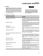
6.2 PURPOSE OF CONTROLS
CONTROL OR INDICATOR
PURPOSE
EMERGENCY STOP SWITCH
Pushing in this switch, found adjacent to the Supervisor
II
, cuts all AC outputs from the latter and de---energizes
the starter. A fault message (E STOP) is displayed by
the Supervisor
II
until the button is pulled out and the
“O”
pad is pressed.
MOTOR O/L RESET
Momentarily pushing this button, found on the thermal
overload element housing in the starter box, re---closes
the latter’s contacts after a current overload takes place.
Please be aware that the elements must be allowed to
cool sufficiently before resetting.
LIMIT SWITCH
Operates blowdown valve.
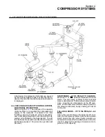
DISCHARGE CHECK VALVE
Isolates compressor from field pipework when shut
down. Located between the HPsilencer and the after-
cooler.
PRESS RELIEF VALVES
Found on the discharge pipework of both LP and HP
stages, they vent the compressed air to atmosphere in
case of an over pressure condition --- 65 and 165 psi
(4.5 and 11.4 bar), respectively.
INLET VALVE CYLINDER AND CONTROL VALVE
ASSEMBLY
The hydraulically operated butterfly valve throttles the
air flow entering the unit inlet flange --- LP stage. A
4---way electric solenoid valve loads and unloads the hy-
draulic actuator, in response to Supervisor
II
com-
mands.
BLOWDOWN VALVES
The 2---way valve vents compressed air (HP discharge)
to atmosphere through a muffler.
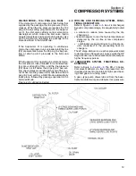
DRAIN GLOBE VALVES
Furnished as manual backups to automatic drain valves
used in the condensate separator vessels. Also used as
lubricant sump drain valve.
OIL PRESSURE BYPASS VALVE
To maintain desired oil flow
and
to protect oil pump from
over pressure situations.
THERMAL VALVE
This thermal valve automatically opens/closes to by-
pass warm oil around the heat exchanger to ensure fast
oil warmup and optimize operating temperature.
SUMP SIGHT GLASS
Indicates level of lubricant in the sump. Located on the
sump side, it should show 75% full (compressor
stopped) for proper oil level.
Содержание DR-13 Series
Страница 6: ...NOTES ...
Страница 14: ...8 NOTES ...
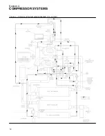
Страница 18: ...Section 4 COMPRESSOR SYSTEMS 12 Figure 4 5 Piping and Instrumentation Diagram Air cooled ...
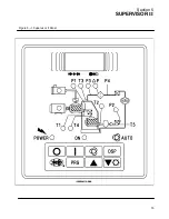
Страница 21: ...Section 5 SUPERVISOR II 15 Figure 5 1 Supervisor II Panel ...
Страница 28: ...22 NOTES ...
Страница 32: ...26 NOTES ...
Страница 42: ...Section 7 MAINTENANCE 36 Table 1 Installation Data ...
Страница 46: ...40 NOTES ...
Страница 48: ...Section 9 ILLUSTRATIONS AND PARTS LIST 42 9 3 COMPRESSOR MOTOR AND FRAME ...
Страница 50: ...Section 9 ILLUSTRATIONS AND PARTS LIST 44 9 4 AIR INLET SYSTEM ...
Страница 52: ...Section 9 ILLUSTRATIONS AND PARTS LIST 46 9 5 COOLER ASSEMBLY ...
Страница 54: ...Section 9 ILLUSTRATIONS AND PARTS LIST 48 9 6 LP HOT LP COLD ...
Страница 56: ...Section 9 ILLUSTRATIONS AND PARTS LIST 50 9 7 HP DISCHARGE ...
Страница 58: ...Section 9 ILLUSTRATIONS AND PARTS LIST 52 9 8 LUBE SYSTEM ...
Страница 60: ...Section 9 ILLUSTRATIONS AND PARTS LIST 54 9 9 ELECTRICAL BOX ...
Страница 62: ...Section 9 ILLUSTRATIONS AND PARTS LIST 56 9 10 CONTROL SYSTEM CONDENSATE DRAIN ...
Страница 64: ...Section 9 ILLUSTRATIONS AND PARTS LIST 58 9 11 CANOPY ...
Страница 66: ...Section 9 ILLUSTRATIONS AND PARTS LIST 60 9 12 DECALS ...
Страница 68: ...Section 9 ILLUSTRATIONS AND PARTS LIST 62 9 12 DECALS ...
Страница 70: ...Section 9 ILLUSTRATIONS AND PARTS LIST 64 9 12 DECALS ...
Страница 72: ...Section 9 ILLUSTRATIONS AND PARTS LIST 66 9 13 DECAL LOCATIONS ...
Страница 74: ...Section 9 ILLUSTRATIONS AND PARTS LIST 68 9 13 DECAL LOCATIONS ...
Страница 76: ...Section 9 ILLUSTRATIONS AND PARTS LIST 70 9 13 DECAL LOCATIONS ...
Страница 78: ...Section 9 ILLUSTRATIONS AND PARTS LIST 72 9 14 WIRING DIAGRAM ...
Страница 79: ...NOTES ...


