Section 7
MAINTENANCE
33
5. Final discussion with maintenance engineer.
This service, when supplemented by properly
recorded package operational performance and
vibrations trends, is most helpful in identifying the
presence (or absence) of equipment damage which
can be repaired or replaced before a catastrophic
breakdown occurs.
7.9 PARTS REPLACEMENT AND ADJUSTMENT
PROCEDURES
Please, familiarize yourself with the safety guide-
lines offered in Section 1 of this manual before
attempting any maintenance on the package.
7.9.1 AIR FILTER INSPECTION/MAINTENANCE
ELEMENT INSPECTION
1. Place a bright light on one side of each element
to inspect for damage or leak holes.
2. Inspect gaskets and matching sealing surfaces
on the housing. It should be smooth or replace in
case of damage.
3.
DO NOT
strike elements against a hard surface
to dislodge dirt - this may damage the sealing sur-
faces and/or rupture the element.
AIR FILTER MAINTENANCE
. Air filter maintenance should
be performed at 8000 hours, one year or when the
corresponding maintenance message is displayed
by the controller. This corresponds to a pressure
loss condition across the filter of 12 in. (30.5 cm) of
water. Your filter assembly includes a pre-filter ele-
ment and a main element.
1. Loosen screws and remove access panel.
2. Remove the pre-filter and main filter elements.
3. Clean interior of housing with a damp cloth.
4. Replace the pre-filter element with new element.
NOTE: pre-filter can be cleaned by washing with
water.
5. Replace the main element with new element.
6. Replace access door and tighten retaining
screws.
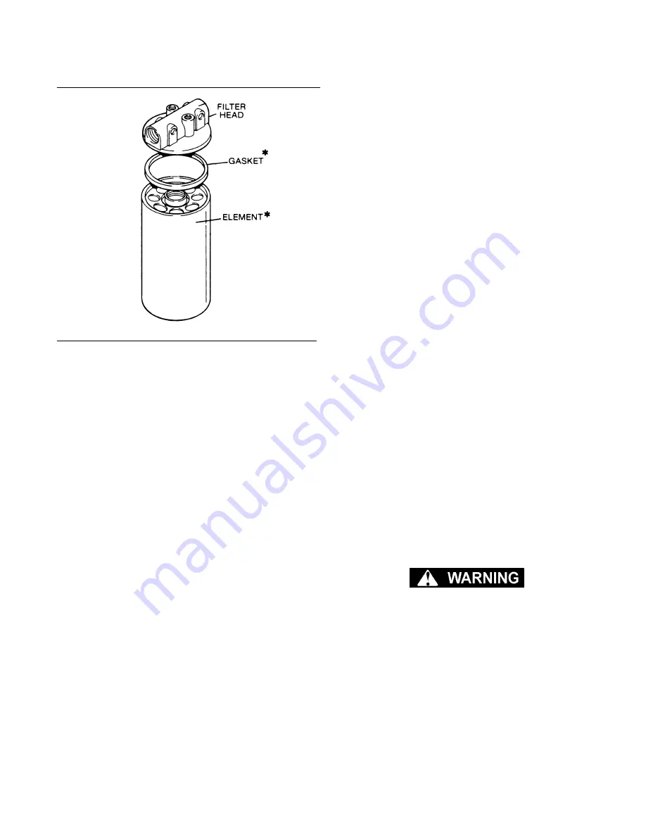
7.9.2 OIL FILTER MAINTENANCE
. Oil filter maintenance (using
repair kit P/N 02250049-820) should be performed
at 8,000 hours, one year or when the corresponding
maintenance message is displayed by the con-
troller - this corresponds to a pressure loss condi-
tion across the unit of 20 psi (1.4 barg). Your oil fil-
ter includes a proprietary replaceable element (P/N
02250049-821) available solely from Sullair and its
agents -
DO NOT
substitute.
1. Using a strap wrench, remove the old element
and gasket.
2. Clean the gasket seating surfaces.
3. Apply a light film of fresh oil to the new gasket
and hand-tighten new element until gasket contacts
the seat.
4. Continue tightening element by hand, an addi-
tional 1/2 to 3/4 turn.
5. Restart package and check for leaks.
7.9.3 CONTROL LINE FILTER MAINTENANCE
02250112-032) maintenance normally requires
replacement of the filter element, float assembly
and seals. Use repair kit no. 02250112-031 (filter
element and seal), and repair kit no. 02250115-960
(float assembly and seals).
DO NOT remove caps, plugs, and/or other com-
ponents when compressor is running or pres-
surized.
Stop compressor and relieve all internal pres-
sure before doing so.
1. Detach the body from the bowl by twisting the
body about the bowl as far as it can go (approxi-
mately 1/8 turn), and pulling apart.
2. At this time, unscrew the baffle from the body.
Remove the element.
3. Discard the element.
4. Replace the element with the new one found in
Figure 7-3 Oil Filter (P/N 02250049-820)
*Replacement Element P/N 02250049-821
Содержание DE-18
Страница 6: ...NOTES...
Страница 14: ...8 NOTES...
Страница 18: ...12 NOTES...
Страница 23: ...Section 4 COMPRESSOR SYSTEMS 17 Figure 4 4 Piping and Instrumentation Diagram...
Страница 25: ...19 NOTES...
Страница 26: ...Section 5 CONTROLLER 20 Figure 5 1 Control Panel...
Страница 32: ...26 NOTES...
Страница 36: ...30 NOTES...
Страница 51: ...45 NOTES...


