


SECTION 1
7
E.
Flow-limiting valves are listed by pipe size and
rated CFM. Select appropriate valve accordingly.
F. DO NOT
use tools that are rated below the maxi-
mum rating of this compressor. Select tools, air
hoses, pipes, valves, filters and other fittings
accordingly.
DO NOT
exceed manufacturer’s
rated safe operating pressures for these items.
G.
Secure all hose connections by wire, chain or
other suitable retaining device to prevent tools or
hose ends from being accidentally disconnected
and expelled.
H.
Open fluid filler cap only when compressor is not
running and is not pressurized. Shut down the
compressor and bleed the sump (receiver) to
zero internal pressure before removing the cap.
I.
Vent all internal pressure prior to opening any
line, fitting, hose, valve, drain plug, connection or
other component, such as filters and line oilers,
and before attempting to refill optional air line
anti-icer systems with antifreeze compound.
J.
Keep personnel out of line with and away from
the discharge opening of hoses, tools or other
points of compressed air discharge.
K. DO NOT
use air at pressures higher than 30 psig
(2.1 bar) for cleaning purposes, and then only
with effective chip guarding and personal protec-
tive equipment per OSHA Standard 29 CFR
1910.242 (b) or any applicable Federal, State
and Local codes, standards and regulations.
L. DO NOT
engage in horseplay with air hoses as
death or serious injury may result.
M.
This equipment is supplied with an ASME
designed pressure vessel protected by an ASME
rated relief valve. Lift the handle once a week to
make sure the valve is functional.
DO NOT
lift
the handle while machine is under pressure.
N.
If the machine is installed in an enclosed area it
is necessary to vent the relief valve to the outside
of the structure or to an area of non-exposure.
O. DO NOT
remove radiator filler cap until the cool-
ant temperature is below its boiling point. Then
loosen cap slowly to its stop to relieve any
excess pressure and make sure coolant is not
boiling before removing cap completely. Remove
radiator filler cap only when cool enough to touch
with a bare hand.
P.
The ethyl ether in the replaceable cylinders used
in diesel ether starting aid systems (optional) is
under pressure.
DO NOT
puncture or incinerate
those cylinders.
DO NOT
attempt to remove the
center valve core or side pressure relief valve
from these cylinders regardless of whether they
are full or empty.
Q.
If a manual blowdown valve is provided on the
receiver, open the valve to ensure all internal
pressure has been vented prior to servicing any
pressurized component of the compressor air/
fluid system.
1.4
FIRE AND EXPLOSION
A.
Refuel at a service station or from a fuel tank
designed for its intended purpose. If this is not
possible, ground the compressor to the dis-
penser prior to refueling.
B.
Clean up spills of fuel, fluid, battery electrolyte or
coolant immediately if such spills occur.
C.
Shut off air compressor and allow it to cool. Then
keep sparks, flames and other sources of ignition
away and
DO NOT
permit smoking in the vicinity
when adding fuel, checking or adding electrolyte
to batteries, checking or adding fluid, checking
diesel engine ether starting aid systems, replac-
ing cylinders, or when refilling air line anti-icer
systems antifreeze compound.
D. DO NOT
permit liquids, including air line anti-icer
system antifreeze compound or fluid film, to
accumulate on bottom covers or on, under or
around acoustical material, or on any external or
internal surfaces of the air compressor. Wipe
down using an aqueous industrial cleaner or
steam clean as required. If necessary, remove
acoustical material, clean all surfaces and then
replace acoustical material. Any acoustical mate-
rial with a protective covering that has been torn
or punctured should be replaced immediately to
prevent accumulation of liquids or fluid film within
the material.
DO NOT
use flammable solvents
for cleaning purposes.
WARNING
Do not attempt to operate the compressor
in any classification of hazardous environ-
ment or potentially explosive atmosphere
unless the compressor has been specially
designed and manufactured for that duty.
Содержание 300HH
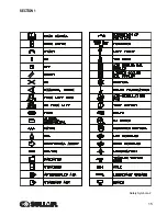
Страница 17: ...SECTION 1 15 Safety Symbols 2 ...
Страница 18: ...SECTION 1 16 Safety Symbols 3 ...
Страница 26: ...300HH 375 375H 375HH 425 AND 425H USER MANUAL R00 SECTION 2 24 Figure 2 6 Piping and Instrumentation ...
Страница 28: ...300HH 375 375H 375HH 425 AND 425H USER MANUAL R00 SECTION 2 26 Figure 2 7 Piping and Instrumentation ...
Страница 49: ...SECTION 2 300HH 375 375H 375HH 425 AND 425H USER MANUAL R00 47 2 9 WIRING DIAGRAM ...
Страница 60: ...NOTES 58 ...
Страница 79: ...NOTES ...