


SECTION
1
4
A.
Prior to hitching the air compressor to the tow
vehicle, inspect all attachment parts and equip-
ment, checking for (i) signs of excessive wear or
corrosion, (ii) parts that are cracked, bent,
dented or otherwise deformed or degraded, and
(iii) loose nuts, bolts or other fasteners. Should
any such condition be present,
DO NOT TOW
until the problem is corrected.
B.
Back the tow vehicle to the compressor and posi-
tion it in preparation for coupling the compressor.
C.
If the compressor is provided with a drawbar
latched in the vertical upright position, carefully
unlatch drawbar and lower it to engage the cou-
pling device. If not, raise drawbar with the jack to
engage coupling device or otherwise couple the
compressor to the towing vehicle.
D.
Make sure the coupling device is fully engaged,
closed and locked.
E.
If chains are provided, pass each chain through
its point of attachment on the towing vehicle;
then hook each chain to itself by passing the
grab hook over (not through) a link. Cross chains
under the front of drawbar before passing them
through points of attachment on towing vehicle to
support the front of drawbar in case it should
accidentally become uncoupled.
F.
Make sure that the coupling device and adjacent
structures on the towing vehicle (and also, if uti-
lized, chain adjustment, brake and/or electrical
interconnections)
DO NOT
interfere with or
restrict motion of any part of the compressor,
including its coupling device, with respect to the
towing vehicle when maneuvering over any
anticipated terrain.
G.
If provided, make sure chain length, brake and
electrical interconnections provide sufficient
slack to prevent strain when cornering and
maneuvering, yet are supported so they cannot
drag or rub on road, terrain or towing vehicle sur-
faces which might cause wear that could render
them inoperative.
H.
On two-wheeled models, fully retract front screw
jack and any rear stabilizer legs. If a caster wheel
is provided on the screw jack it is part of the
screw jack, and can not be removed. Follow the
same procedure for stowing away the wheeled
jack as you would for the standard screw jack.
Pull the pin connecting the jack to the drawbar
and raise the screw jack to its full upright posi-
tion. Rotate the screw jack to its stowed position,
parallel to the drawbar, and reinsert the pin.
Make sure the jack is secured in place prior to
towing.
WARNING
This equipment may be tongue heavy. DO
NOT attempt to raise or lower the drawbar
by hand if the weight is more than you can
safely handle.
Use the screw jack provided or a chain fall
if you cannot lift or lower it without avoiding
injury to yourself or others. Keep hands
and fingers clear of the coupling device and
all other pinch points. Keep feet clear of
drawbar to avoid injury in case it should
slip from your hands.
WARNING
This equipment may be tongue heavy. DO
NOT attempt to raise or lower the drawbar
by hand if the weight is more than you can
safely handle.
CAUTION
Retract the front screw jack only after
attaching the compressor to the tow vehi-
cle. Raise the screw jack to its full up posi-
tion and pull the pin connecting the jack to
the drawbar. Rotate the screw jack to its
stowed position, parallel to the drawbar,
and reinsert the pin. Make sure the jack is
secured in place prior to towing.
If a caster wheel is provided on the screw
jack it is part of the screw jack and can not
be removed. Follow the same procedure for
stowing away the wheeled jack as you
would for the standard screw jack. Pull the
pin connecting the jack to the drawbar and
raise the screw jack to its full up position.
Rotate the screw jack to its stowed posi-
tion, parallel to the drawbar, and reinsert
the pin. Make sure the jack is secured in
place prior to towing.
Содержание 300HH
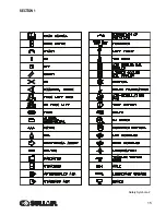
Страница 17: ...SECTION 1 15 Safety Symbols 2 ...
Страница 18: ...SECTION 1 16 Safety Symbols 3 ...
Страница 26: ...300HH 375 375H 375HH 425 AND 425H USER MANUAL R00 SECTION 2 24 Figure 2 6 Piping and Instrumentation ...
Страница 28: ...300HH 375 375H 375HH 425 AND 425H USER MANUAL R00 SECTION 2 26 Figure 2 7 Piping and Instrumentation ...
Страница 49: ...SECTION 2 300HH 375 375H 375HH 425 AND 425H USER MANUAL R00 47 2 9 WIRING DIAGRAM ...
Страница 60: ...NOTES 58 ...
Страница 79: ...NOTES ...