


Figure 3 - Locate DI Water Cartridges
Figure 5 - DI Water Cartridge
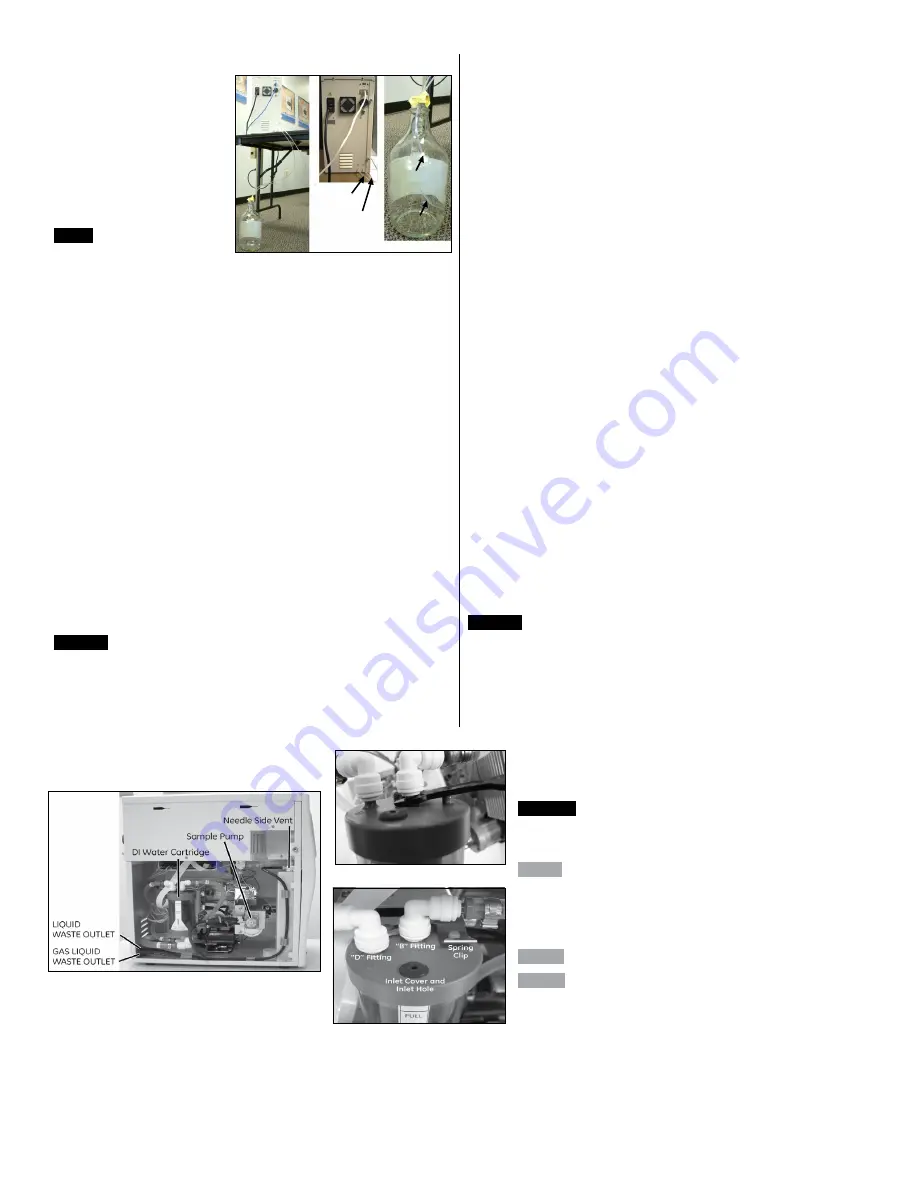
Figure 2 - Route the Waste Lines
2. Connect the end of the tubing with the SwageLok fitting to the
GAS
INLET
port, located on
the back of the Analyzer
(Figure 1). Tighten the
fitting until it is finger-
tight, and then tighten an
additional 1/4 turn using a
7/16" open-ended wrench.
3. Connect the other end
of the tubing to the gas
source.
Step 5
Connect the outlet
ports.
The
LIQUID WASTE
outlet and
GAS LIQUID WASTE
outlet are located on the back of the Analyzer
(Figure 2). Both may be routed to the same waste container, however, the
GAS LIQUID WASTE
line MUST be kept free from submerging in any liquid
to prevent liquid from being drawn back into the Analyzer. Routing the lines
through a waste container and lid with a hole allows you to anchor the
GAS
LIQUID WASTE
line higher in the bottle—completely clear from any liquid
waste.
1. Locate the two flexible tubing sections, each 100 cm long, in the
accessories kit.
2. Take one tubing section and connect one end to the
LIQUID WASTE
port. Push the tubing onto the barbed fitting.
3. Route the other end of the tubing to the waste container, placed
within 90 cm of the Analyzer. The end of the tubing should extend to
the bottom of the container.
4. Take the other tubing section and connect one end to the
GAS
LIQUID WASTE
port. Push the tubing onto the barbed fitting.
5. Route the other end of the tubing to the waste container. The end
of the tubing should extend to approximately the top third of the
container.
Note
: To avoid drawing liquid back into the Analyzer, make
sure the vent line is never submerged in the liquid waste inside the
container.
Step 6
Fill the DI water cartridge.
1. Fill the squeeze bottle (provided in the accessories kit) with DI water.
2. Remove the left side panel of the Analyzer and locate the DI water
cartridge. (Figure 3).
3. Lift the spring clip at the top of the DI water cartridge, and then rotate
the cartridge clockwise (as viewed from the top)
to slide it out of the retaining hooks. (Refer to
Figures 4 and 5 as needed for steps 3-8.)
4. Use the John Guest
®
tool to remove the John Guest fittings labeled
“B” and “D” from the barbs on the top of the DI water cartridge.
5. Install fitting B onto barb D.
6. Remove the rubber inlet cover from the top of the DI water
cartridge.
7. Slide the water bottle nozzle into the inlet hole. Fill the cartridge until
water reaches the FULL line.
8. Replace the rubber inlet cover.
Prime the DI Water Pump
1. Connect the power cord to the Analyzer.
2. Turn the Analyzer
On.
The DI water pump will start in 20-30
seconds.
3. Check for large air bubbles in all the tubing that connects to
the DI water cartridge. If large air bubbles are present, tap or
manipulate the tubing to work the air bubbles out.
4. Keep the Analyzer powered
On
for two minutes, and then turn
the Analyzer
Off
.
5. Wait 30 to 60 seconds and then turn the power
On
again. Allow
the DI water pump to circulate water for at least 10 minutes.
6. Check the tubing that leads to the DI water cartridge. Most of
the air originally in the tubing should be replaced with water. If
more than a few small bubbles remain, turn the Analyzer
Off
and
repeat step 5.
7. Turn the Analyzer
Off
.
8. Remove fitting B from barb D.
9. Re-connect fitting B to barb B, and fitting D to barb D.
10. Slide the DI water cartridge into the bracket and rotate it into the
retaining clip until it snaps into place.
11. Inspect the FULL line on the DI water cartridge. If needed, add
more DI water.
12. Replace the left side panel.
Step 7
Install external devices.
1. To communicate with the DataPlus software, connect the Analyzer
to your computer or computer network. Attach one end of the
Ethernet cable to the Ethernet port located on the back of the
Analyzer. Attach the other end of the cable either to an Ethernet
port on your computer or to a connection to your computer network.
2. Install a Printer (Optional).
You can connect a printer to the USB
port located on the back of the Analyzer. Refer to the
Sievers
860 Laboratory TOC Analyzer Operation and Maintenance
Manual
for complete details.
Step 8
Install the DataPlus Software.
Refer to the
Sievers 860 Laboratory TOC Analyzer Operation
and Maintenance Manual
for complete details.
Step 8 A
Run the DataPlus Software installation program on
the computer.
The program installs to a default "DataPlus" location on the C:
drive. We recommend against installing the application in the
computer’s
Programs
folder.
Step 8 B
Power
On
the Analyzer.
Step 8 C
Obtain the IP address.
The Analyzer can connect to the computer through a network
using a dynamic IP address (default) or a static IP address.
Figure 4 - Remove John Guest Fitting
2
DQS 79000-03 EN Rev. A
"D" Fitting
"B" Fitting
Gas/Liquid
Waste Outlet
Port
Liquid Waste
Outlet Port
Gas/Liquid
Waste Line
Liquid
Waste Line


