Subaru H001SXA000 Скачать руководство пользователя страница 5

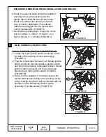
MAIN HARNESS CONNECTIONS (CONTINUED)

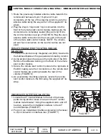
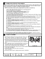
24-PIN AND 2-PIN UPPER LEFT KICK PANEL PRE-

FIT CONNECTIONS

1. Locate the vehicle’s 24-pin and 2-pin pre-fit

connections located in the upper left kick panel area.
These connectors are secured to the vehicle wiring
using breakaway tape. (FIGURE O)

2. When the 2-pin pre-fit connector is located, unplug

and discard the mating wire jumper.

3. Carefully route the remote start harness 24-pin and

2-pin connectors to the upper left kick panel area,
making sure that they will not interfere with any
vehicle moving components and re-assembly of
dashboard panels. (FIGURE P)

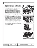
4. Plug the remote start harness 24-pin and 2-pin

males connectors into the corresponding 24-pin and
2-pin vehicle female connectors.

5. Using 2 of the supplied 8” tie wraps, secure the

remote start wiring to existing vehicle wiring.

6. Route the remote start harness programming button

and 30-AMP fuse assembly to the vehicles fuse box
assembly and secure the wiring to existing vehicle
wiring using one of the supplied 8” tie wraps.
(FIGURE Q). DO NOT SECURE THE REMOTE
START HARNESS TO ANY VEHICLE YELLOW
HARNESSES / CONNECTORS (AIRBAG SYSTEM).

PART NUMBER

H001SXA000

5 OF 10

ISSUE

01

DATE

03/1

4

/06

SUBARU OF AMERICA

FIGURE P

FIGURE O

FIGURE Q

Содержание H001SXA000

Страница 1: ...wdriver Short and Standard Panel Removal Tool Alcohol and Towel CAUTION DO NOT SECURE ANY REMOTE START HARNESSES MODULES TO ANY YELLOW HARNESSES CONNECTORS AIRBAG SYSTEM IN THE VEHICLE T Remove Instal...

Страница 2: ...3 Using a panel removal tool carefully remove the driver s side lower center console panel FIGURE C 4 Using a phillips screwdriver remove the 3 plastic phillips fasteners holding the driver s under d...

Страница 3: ...knee bolster by removing the 4 10mm bolts FIGURE H FIGURE F FIGURE G FIGURE H VEHICLE PREPARATION CONTINUED WINDSHIELD MOUNT ANTENNA INSTALLATION 5 1 Locate the position at the top of the windshield...

Страница 4: ...s 1 5 ft lbs FIGURE J MAIN HARNESS CONNECTIONS 6 WAY IGNITION SWITCH CONNECTIONS 1 Locate the 6 pin ignition switch connector on the left side of the steering column and unplug FIGURE L 2 Plug the rem...

Страница 5: ...with any vehicle moving components and re assembly of dashboard panels FIGURE P 4 Plug the remote start harness 24 pin and 2 pin males connectors into the corresponding 24 pin and 2 pin vehicle femal...

Страница 6: ...GURE R IMMOBILIZER INTERFACE MOUNTING 1 Locate the A T Control Module to the left of the brake pedal Using alcohol clean an area on the A T control module metal bracket Using the supplied velcro and 2...

Страница 7: ...lumn shroud Re secure the previously loosened phillips screws securing the upper steering column shroud to the steering column assembly FIGURE W 4 Route the immobilizer interface antenna ring wiring t...

Страница 8: ...safety switch wiring harness to the base of the hood safety switch FIGURE Z PART NUMBER H001SXA000 8 OF 10 ISSUE 01 DATE 03 14 06 SUBARU OF AMERICA 9 FIGURE Y FIGURE Z T UNDER HOOD WARNING LABEL MOUNT...

Страница 9: ...mode 7 Start the vehicle with the ignition key The RES system will begin honking the vehicle s horn 1 time every 3 seconds to indicate a valid tach signal 8 When the engine has settled to a normal id...

Страница 10: ...remove the 3rd key 17 Press and release the remote start system programming button one time to access Immobilizer Interface Registration Mode 18 Activate the remote start system by pressing the trans...

Отзывы: