7001575 -
UC Door Lock Kit Instructions
7014581 / Rev B / August, 2011
CONTAINS:
QTY DESCRIPTION
1
Lock, Door w/ Keys and Nut
1
Cam, Lock (Offset Cam)
4
Screw, #10-24x1/2 Tamper Proof
Appliance can be laid on its back to allow easier installation of these components, but not neseccary. If
appliance is laid on its back, be sure to use proper lifting techniques. When done with component instal-
lation be sure to allow unit to stand upright a minimum of 24 hours before connecting power. This will
allow the oil to return to the compressor.
PROCEDURE:
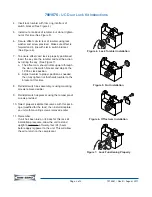
1.
Remove kickplate by extracting its mounting
screws from each side, then pull kickplate forward
(See Figure 1).
2.
Remove switch depressor from bottom of door by
extracting its two mounting screws, then pull
switch depressor from door (See Figure 2).
3.
Remove switch bracket from cabinet bottom by
extracting its two mounting screws, one each
side, then pull switch bracket down and forward
as far as wires will allow (See Figure 3).
NOTES:
•
This is a very tight space. An offset screw-
driver will make this task easier.
•
It is not neseccary to disconnect eletricals
from switch, but doing so will make lock
installation easier.
Page 1 of 2
QTY DESCRIPTION
1
Kickplate, Stainless Steel
1
Kickplate, U/C 24 (Black)
1
Instructions
Figure 1. Kickplate Removal
Figure 3. Switch Bracket Removal
Figure 2. Switch Depressor Removal
NOTE:
Door and
Switch electricals
were removed from
diagram for clarity.
SHOCK HAZARD! DISCONNECT POWER TO UNIT BEFORE ATTEMPTING TO THIS PROCEDURE.
DOOR
NOTE:
This lock kit can also be used on the model 424 if the serial number prefix is a “P”. If the serial number
prefix is an “M” or an “F” this lock kit will not fit.


