background image

31

 © STULZ GmbH – all rights reserved EN/06.2021/G23

minispace cw original instructions

5.4.1 Condensate drain connection

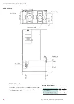
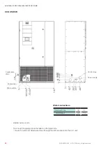
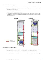
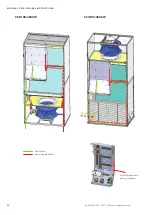
The position of the condensate drain is marked in the preceding schemes for the pipe entrance areas.
The internal diameter of the syphon is 22 mm.

In upflow units the condensate connection is designed in the form of a plastic hose nozzle with an external 
diameter of 22 mm.

  InForMATIon

Comply with the regulations of the local water supply authority. 

•  Connect the condensate water drains to the local waste water system.


CAUTIon

risk of injury from sharp edges

The fins of the heat exchanger and the condensate drip tray are sharp-edged. Wear safety 

gloves and cover forearms.

Содержание CyberAir Mini CW

Страница 1: ...CyberAir Mini CW Original instructions Precision Air Conditioning Units 400V 50Hz 3Ph N PE Index G23 Issue 6 2021...

Страница 2: ...g technology business spe cialising in A C for data centres and telecommunications installations STULZ has ten production plants 2 in Germany Italy the USA Great Britain Spain 2 in China Brazil and In...

Страница 3: ...energy efficient and noise optimized unit series for small to medium heat loads These modern and maintenance friendly units require only a small footprint and can be easily installed in existing rooms...

Страница 4: ...4 4 EN 06 2021 G23 STULZ GmbH all rights reserved Cyberair mini CW original instructions...

Страница 5: ...mance data CCU CW 14 4 4 Dimensional drawings 15 5 Installation 18 5 1 Selection ofthe installation site 18 5 2 Positioning the unit 20 5 3 Opening the A C unit 21 5 4 Water piping connection 22 5 4 1...

Страница 6: ...ation notice esd note risk of damaging electronical components 1 2 Safety instructions These operating instructions contain basic information which is to be complied with for installation operation an...

Страница 7: ...termination of emergency measures accidents malfunctions Creation of an abbreviated instruction and notification template page a A unit protocol must be kept b To be stored in the proximity ofthe unit...

Страница 8: ...ceive the consignment papers with the delivery ofthe A C unit The shipment is made ex works in case of shipment damages please assert your claim towards the carrier 2 2 Transport danger Mortal danger...

Страница 9: ...installation the following measures have to be carried out to protect the unit from damage and corrosion the storage point must not be exposed to direct sunlight Observe the storage conditions in the...

Страница 10: ...ariant ofyourA C unit and can be found on the rating plate The rating plate is located in the door in front ofthe electric box internal part no Order number alternative Serial no Unit type Page code E...

Страница 11: ...er by means of a 0 10V signal At the air inlet a temperature and humidity sensor is installed The setpoints can be set at the controller To control the supply airtemperature the controller adjusts the...

Страница 12: ...pen dent ofthe supplyvoltage and can be found in this manual Requirements for electric network and UPS systems the output voltage ofthe electric network or UPS sys tem must be grounded neutral wye the...

Страница 13: ...0 7 5 Chloride content mg l 100 Chloride content with austenitic steels mg l 50 Free chlorine mg l 0 05 Hydrogen sulphide mg l 0 05 Ammonia NH3 NH4 mg l 0 05 Sulphate mg l 100 Manganese mg l 0 05 Iro...

Страница 14: ...gr e 2 Wege DN20 DN25 DN32 Wasserinhalt W rmetauscher dm 5 9 12 14 Schalldruckpegel dBA 46 53 55 58 Baugr e 1 2 3 4 Leergewicht kg 139 169 204 237 EN 06 2021 G23 STULZ GmbH all rights reserved minispa...

Страница 15: ...15 Downflow Upflow STULZ GmbH all rights reserved EN 06 2021 G23 minispace cw original instructions 4 4 Dimensional drawings Cabinet size 1 Cabinet size 2...

Страница 16: ...16 Downflow EN 06 2021 G23 STULZ GmbH all rights reserved minispace cw original instructions Cabinet size 3 Cabinet size 4...

Страница 17: ...17 Upflow STULZ GmbH all rights reserved EN 06 2021 G23 minispace cw original instructions Cabinet size 3 Cabinet size 4...

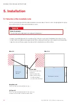
Страница 18: ...als may not have access to the installation site ofthe A C unit check that the installation site is appropriate forthe unit weight which you can read in the technical data take into account the necess...

Страница 19: ...19 min 0 5 m STULZ GmbH all rights reserved EN 06 2021 G23 minispace cw original instructions Air intake area for Downflow units Air outlet area for Upflow units without duct connection...

Страница 20: ...ear safety boots safety gloves and helmet Mounting aids Pallet height Transport with a fork lift transport the A C unit on the pallet as close as possible to the installation site unscrewtransport loc...

Страница 21: ...l pins and can be removed without auxiliary equipment To remove this panel first open the door using the male triangularwrench provided Open the doorwide and secure it against swinging shut again This...

Страница 22: ...ystem and the A C unit take the position ofthe connections out ofthese drawings to conduct the lines to the unit notice Water remaining from the test run may escape when the protective caps are remove...

Страница 23: ...piping notice the labels on the pipe ends Route the external chilled water lines through the raised floor into the A C unit All dimensions in mm Water connections Chilled water line DN 20 Male thread...

Страница 24: ...e piping notice the labels on the pipe ends Route the external chilled water lines through the raised floor into the A C unit All dimensions in mm Water connections Chilled water line DN 25 Male threa...

Страница 25: ...piping notice the labels on the pipe ends Route the external chilled water lines through the raised floor into the A C unit All dimensions in mm Water connections Chilled water line DN 32 Male thread...

Страница 26: ...piping notice the labels on the pipe ends Route the external chilled water lines through the raised floor into the A C unit All dimensions in mm Water connections Chilled water line DN 32 Male thread...

Страница 27: ...o connect the piping notice the labels on the pipe ends Route the external chilled water lines through the left side panel into the A C unit All dimensions in mm Water connections Chilled water line D...

Страница 28: ...To connect the piping notice the labels on the pipe ends Route the external chilled water lines through the left side panel into the A C unit All dimensions in mm Water connections Chilled water line...

Страница 29: ...o connect the piping notice the labels on the pipe ends Route the external chilled water lines through the left side panel into the A C unit All dimensions in mm Water connections Chilled water line D...

Страница 30: ...o connect the piping notice the labels on the pipe ends Route the external chilled water lines through the left side panel into the A C unit All dimensions in mm Water connections Chilled water line D...

Страница 31: ...the syphon is 22 mm In upflow units the condensate connection is designed in the form of a plastic hose nozzle with an external diameter of 22 mm information Complywith the regulations ofthe local wat...

Страница 32: ...ction cable is de energized The electric cables are onlyto be connected by an authorized specialist notice Make sure that the phase rotation is correct the rotating field must turn right Otherwise a t...

Страница 33: ...unit shall be connected to other Stulz units bythe pLAN bus to a BMS or contains opional exten sions as dampers you must route control lines and connect them in the electric box ofthe A C unit route...

Страница 34: ...34 CCU 180 350 CW CCD 180 350 CW EN 06 2021 G23 STULZ GmbH all rights reserved minispace cw original instructions control line power supply cable customer power out put e g for pump...

Страница 35: ...0 until 25 2 C 45 until 30 8 C 50 until 37 6 C Propylene glycol Water or outside airtemperature 25 until 10 7 C 30 until 14 0 C 35 until 17 6 C 40 until 21 5 C 45 until 26 0 C 50 until 32 4 C 6 1 Fill...

Страница 36: ...ll the chilled water circuit by means ofthe filling connections see hydraulic diagram part ofthe unit documents bleed airfrom the chilled water circuit by means ofthe schradervalves for bleeding Elect...

Страница 37: ...ing the Start Stop key on the Touch display caution Risk of injury by fan rotation The front door and the lower panel represent a protective device During operation the front door panel and the rear p...

Страница 38: ...unit at the controller and at the master switch display a DO NOT SWITCH ON warning sign switch off power conducting cables to the unit and secure them against being switched on again check to ensure...

Страница 39: ...via the controller is released The controller can be configured such as to compensate the pressure loss by a higherfan speed howeveryou should not wait too long for exchanging the filter In upflow uni...

Страница 40: ...ea ofthe fan The outlet area is in the raised floorfor downflow units and above the unit for upflow units caution Fracture or loss of limbs The running fan can suck in and draw in loose clothing Befor...

Страница 41: ...on time of 30 days Unit interior Clean pipes simplifythe search for leaks clean the unit s inside with a vacuum cleaner Vibrations of pipes and circuit components can result in leaks check the pipes f...

Страница 42: ...The tolerance to the average value adjustable in the control ler has been exceeded 1 Big difference of measured val ues in selected zone Check room on Hotspots or chilled air zones moist zones Check m...

Страница 43: ...he de energized network caution If glycol or similar additives had been used this liquid has to be collected and disposed in an appropriate manner and may under no circumstances be introduced in the l...

Страница 44: ...tives and EC safety standards listed below In the case of a modification ofthe equipment not co ordinated with us this declaration loses its validity Air conditioning unit 10 Contents of the CE Declar...

Страница 45: ...werthan the actual output the inlet valve is closed until the desired capacity is achieved by lowering ofthe water level evaporation process Level monitoring A sensor provided in the steam cylinder co...

Страница 46: ...0Hz 4 0 3 0 4 6 3 8 5 7 4 7 8 0 6 0 9 1 7 5 11 4 9 4 15 0 11 25 17 1 14 1 21 4 17 6 A reverse osmosis plant ROP can be used to soften water The waterfrom the ROP has a low conductivity and must be mix...

Страница 47: ...or steam cylinder F1 Fuse control board 2 A time lag F2 Q2 Automatic fuse control voltage F3 Q3 MCB humidifier H1 Red LED Error H2 Yellow LED Service Warning H3 Green LED Steam production JP1 Jumper b...

Страница 48: ...the control unit ECCM S is not activated Fault No 4 steam cylinder maintenance due 72 hours afterthe warning an error is triggered and the unit is switched off red LED lights However the error switch...

Страница 49: ...valve 5 Outlet valve 6 Drain connector 30 mm 7 Water supply connector G 3 4 notice We recommend the installation of an Aqua stop valve in the water supply ofthe humidifier In addition to this the room...

Страница 50: ...a pressure reducing valve set to 4 6 bar In each case it is to be ensured that the manufactured water pipe upstream ofthe connection to the humidifier is flushed properly We recommend only using copp...

Страница 51: ...ifthe cylinder maintenance is due orthe maintenance indication is not reset afterthe maintenance in info mode LED blinks in intervals if a malfunction with status warning is present The number of blin...

Страница 52: ...um steam capacity 1 Briefly press the drain info key The heating voltage is interrupted and the drain valve opens The yellow LED blinks Note the drain valve closes after 10 minutes automatically 2 To...

Страница 53: ...for a short time orwhether it can resolve the problem bytaking necessary measures Red LED Error blinks intermittently The control unit after several attempts fails to solve the problem number of atte...

Страница 54: ...inthewatersupplypipe clean water inlet filter check water pressure inspect replace inlet valve Inspect steam installation Clean replace drain valve notice Ifthe Jumper L is removed from the ECCM S con...

Страница 55: ...set to an invalid position Set rotary switch on control unit ECCM S to the position forthe corresponding steam cylinder type see chapter 11 1 1 3 11 1 4 5 Replacement of fine wire fuse on the control...

Страница 56: ...enance GH Gesamth rte DT Duret totale TH Total hardness Service intervals for steam cylinder depending on steam production in hours Life time range Time hours You find a detailed description ofthe mai...

Страница 57: ...cted in accordance with the electric diagram It is controlled and monitored by the controller Set the values for switching on and off on the controller Referto the operating instructions ofthe control...

Страница 58: ...the left side with a male thread connect the pipelines to an external hot water circuit Commissioning No measures are required for commissioning Malfunction causes Alarm Reheat failure A heating alarm...

Страница 59: ...size 11 3 Air side connection 11 3 1 Unit base The unit base is available in the versions open with damper with flexible connection orwith supply grilles The unit base can be installed in two ways wi...

Страница 60: ...2021 STULZ GmbH all rights reserved air side connection Unit base with damper Unit base with flexible connection Unit base with grilles The standard grilles are equipped with horizontal fins which ca...

Страница 61: ...With this option for upflow units the front panels are not provided with an air inlet perforation as otherwise usual The air is drawn in from the bottom in consequence there is no unit bottom plate T...

Страница 62: ...5 421 5 421 5 A B C D E H EN 06 2021 STULZ GmbH all rights reserved air side connection 11 3 3 Plenum Discharge plenum with front and side grilles The plenum has three air inlet outlet openings that...

Страница 63: ...3 879 1075 STULZ GmbH all rights reserved EN 06 2021 air side connection The A C unit features a closed unit bottom and a grille in the lower section ofthe front Air discharge zone keep clear 11 3 4 A...

Страница 64: ...on unit top The adapter plate serves to attach an air duct on top ofthe unit Attach the adapter plate to the unit with the self tapping screws provided Open the front door If it is a downflow unit pu...

Страница 65: ...on the adapter plate with the enclosed screw connections so that the actuator is on the left and the orange housing is facing backwards Route the cable as shown on the following page Attach the adapt...

Страница 66: ...d lies rolled up on the filter element Provide opening 1 with a rubber grommet from the accessory pack Place the assembly of adapter plate and damper on the A C unit and leave a free space on the side...

Страница 67: ...tor rotates slowly the running time from fully open to fully closed is 150 seconds The torque ofthe actuator is 20 Nm Due to the geometry ofthe blades a force of 660 N is generated during closing when...

Страница 68: ...led openings to seal the adapter plate Damper Connect the enclosed cable at the actuator according to the enclosed manufacturer s instructions Place the damper so that the protruding axis on which the...

Страница 69: ...shows the adapter plate with the outlines ofthe damperframe indicated by a dashed line A section through a downflow unit is projected onto it on which you can see the position ofthe supply lines in th...

Страница 70: ...The picture shows the adapter plate with the outlines ofthe damperframe indicated by a dashed line A section through a downflow unit is projected onto it on which you can see the position ofthe supply...

Страница 71: ...he picture shows the adapter plate with the outlines ofthe damperframe indicated by a dashed line A section through a downflow unit is projected onto it on which you can see the position ofthe supply...

Страница 72: ...The picture shows the adapter plate with the outlines ofthe damperframe indicated by a dashed line A section through a downflow unit is projected onto it on which you can see the position ofthe supply...

Страница 73: ...Plenum The FCP is an option for downflow units It is possible to mix outside airwith return airvia a damper on the back ofthe FCP You receive the FCP as an assembled unit as shown opposite The FCP mus...

Страница 74: ...d routed on the left side wall and lies rolled up on the filter element Place the FCP on the A C unit Push the FCP into the mounting rail from the front Lift the FCP at the front by 150 200 mm and pla...

Страница 75: ...raised floor stand 11 4 Raised floor stand The floor stand is used to adjust the height ofthe A C unit to the existing raised floor and consists of an encir cling rectangular profile of galvanized ste...

Страница 76: ...0 mm longerthan the raised floor stand dimensions Close the joint with a continuous seal The raised floor cutting notch should at least be 15 and must not have any contact to the raised floor stand wh...

Страница 77: ...ircumstances diagonally use mounting aids to bring in the unit and secure these byfixing belts at the A C unit lay at least two securing instruments e g square steel bars on the stand to avoid a slip...

Страница 78: ...4 EN 04 2021 STULZ GmbH all rights reserved raised floor stand...

Страница 79: ...e set at the time relay preadjusted 10 seconds power supply 2 is switched onto the unit The unit starts bythe automatic restart which is integrated in the controller When the voltage of power supply r...

Страница 80: ...limit values and the phase imbalance within the adjusted tolerance the A C unit is restarted automatically Forthis the parameter Phase restart must be set to 1 in the controller When a limit value is...

Страница 81: ...delta voltage must be set Example Network 3 400V PE setting 400V Network 3 480V PE setting 480V Ifthere is a neutral conductor the phase to neutral voltage must be set Example Network 3 400V N PE sett...

Страница 82: ...4 EN 04 2021 STULZ GmbH all rights reserved electrical options Factory setup or in case of spare part delivery Customer setup...

Страница 83: ...it is equipped with a damper a timer in the E box ensures the delayed start ofthe fans afterthe damper is opened The assignment ofthe outputs can be set customer specifically and is documented in the...

Страница 84: ...6 EN 04 2021 STULZ GmbH all rights reserved electrical options Wiring diagram of the circuit board...

Страница 85: ...m contact is triggered at a water level of 40 mm inside the pump tank The pump motor is protected by a thermal fuse At a temper ature of 130 C the motor is switched off and automatically switched on a...

Страница 86: ...circuit breaker according to the standard IEC 345 For a power supply out ofthe A C unit you can use the option M99209 Power supplyfor condensate pump Connect the lines ofthe alarm contact black grey...

Страница 87: ...ing and humidification in air conditioning units The operation is controlled by a float switch depending on the level An alarm contact is triggered when the water level inside the pump tank is too hig...

Страница 88: ...l is too high the contact is opened and an alarm is triggered The drain pipe must have an internal diameter of 10 mm Connect a flexible plastic hose at the water outlet ofthe pump Considerthe performa...

Страница 89: ......

Страница 90: ...0 32 32 Fax 64 9 360 21 80 sales stulz co nz singapore STULZ Singapore Pte Ltd Tel 65 6749 2738 Fax 65 6749 2750 andrew peh stulz sg South Africa STULZ South Africa Pty Ltd Tel 27 0 11 397 2363 Fax 27...

Отзывы: