


Operating manual Digital Transmitter DTM.OCS.S / DTM.OCS.S/N
Communication with the DTM.OCS.S transmitter
Doc-Nr. 10.00.0430
13
5
Communication with the DTM.OCS.S transmitter
5.1
Summary
Communication with the DTM.OCS.S is accomplished via an
RS485 serial interface using Modbus protocol transfers at 9600
baud. STS specific, proprietary commands are transmitted as
ASCII strings embedded in Modbus compatible data frames.
Modbus standard function codes are supported as well.
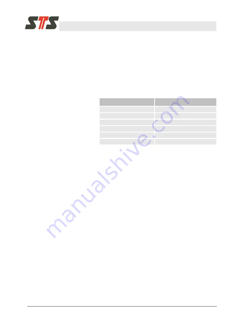
The following settings apply:
Type
Setting
Transmission mode
Modbus RTU
Default address
240
10
Transmission rate
9600 baud
Data bits
8
Parity
None
Stop bits
2
Tab. 2: Settings
5.2
Physical interface
For communication with the DTM.OCS.S, a suitable interface such
as a Modbus compatible RS485-USB converter must be employed.
5.3
Software interface
5.3.1
Modbus
Modbus is a master-slave communication protocol.
Slave devices will never communicate with each other.
Modbus telegrams in the RTU mode always begin with the
address (0 - 247) and a function code (FC Code). Then the data
words (DW) follows. 2 bytes with the CRC checksum form the
conclusion.
The function code indicates to the device what action to
perform.
Communication states (transmit/receive/cancel) are controlled
via timeouts.
The byte sequence for transmission of data words and the CRC
checksum is defined as follows:
Data words:
Hi
– Lo byte
CRC:
Lo
– Hi byte
For the communication with the DTM.OCS.S, standard Modbus
commands (Function Codes 3, 4 and 16) and a custom STS
function code (0x64 [100
10
]) are used.
Содержание DTM.OCS.S
Страница 2: ...2 Doc Nr 10 00 0430...