background image

32 

Integrated Electronic 

 Microprocessor Controller 

Read And Save These Instructions - Page 1 of 3 

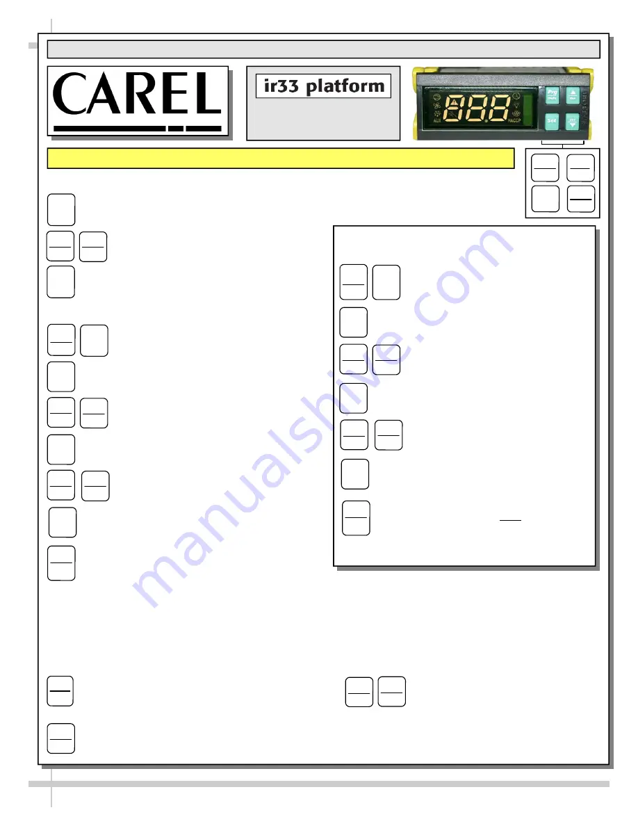
Programming The Instrument 


To Modify The Setpoint 


Press and hold the “SET” key for at least 1 second. 


2. Use arrow keys 


 on temperature      

controller to increase (or decrease) the        
setpoint. 


3. Quickly press and release the “SET” key again. 


To Modify Defrost, Differential, Other Parameters 


1.  Press & hold “Prg” & “SET” keys together                                          
for five (5) seconds; display will flash “0”,                
representing password prompt. 


2. Confirm by pressing “SET” key. 


3. Press 

 or 

 to reach the 

category to be modified. 


4. Press “SET” to modify this selected parameter. 


5. Increase or decrease the value using 
the 

 or 

 button respectively. 


6. Press the “SET” key to temporarily save the new 
value and return to the display of the parameter. 


7. Press & hold the “Prg” key for at least 5 seconds 
to save changes.  This action will also mute the 
audible alarm (buzzer) & deactivate the alarm relay. 


Warning!  Save Your Parameter Settings! 


1.  To store the new parameter values, PRESS and HOLD the “Prg” key for at least 5 seconds.  
2.  All modifications made to parameters will be lost if you do NOT press a button within 60 seconds. Should 
this “timeout” occur, normal operational settings (prior to modifications being made) will resume. 
3.  If the instrument is switched off before pressing the “Prg” key, all modifications to parameters will be lost.   

Set 

Set 


aux 

Prg 

mute 

def 


Prg 

mute 

Set 

Set 

def 


Set 


aux 


aux 

def 


Set 

Prg 

mute 

Oper Manuals - PUB\Templates\Carel Controller\Carel Controller IR33.pub 

This data derived from Carel Material: ir33 +030220441 - rel. 2.0 - 01.05.2006


How To Change Reading From 

Fahrenheit (°F) To Celsius (°C) 


1. Press and hold “Prg” and “SET” keys 
together for at least 5 seconds; display 
will show “0” (password prompt). 


2. Confirm by pressing “SET” key. 


3. Press 

 or 

 until reaching the 

parameter “/ 5”. 


4. Press “SET” to modify this selected 
parameter. 


5. Press 

 or 

 to change value to 

desired setting: “0” for Celsius (°C) or 
“1” for Fahrenheit (°F). 


6. Press “SET” key to temporarily save the 
new value and return to the display of the 
parameter. 


7. Press & hold “Prg” key for at least 5 
seconds to save changes.  

Note!  All values 

will automatically convert to new scale.  No 
conversion is required.


Prg 

mute 

Set 

Set 

def 


aux 

Set 


aux 

def 


Set 

Prg 

mute 

Set 

def 


aux 

To Activate / Deactivate Auxiliary Output


Press and hold the “aux” key for 1 second.


aux 

To Activate Manual Defrost 


 Press and hold “def” key for at least 5 seconds. 

def 


To Reset Any Alarms With Manual 
Reset 


Press and hold the “Prg” and “aux”  

                    key for at least 1 second.


aux 

Prg 

mute 

Содержание Harmony HMO3936R

Страница 1: ...O5136R 4716 HMO5136R 7121 HMO7236R 4716A and HMO7536R Note This Manual May Also Be Applicable To Models Not Listed Herein 888 E Porter Road Muskegon MI 49441 Phone 231 798 8888 Fax 231 798 4960 www st...

Страница 2: ...ATING INSTRUCTIONS OPTIONAL SERIAL LABEL INFORMATION LOCATION CLEANING SCHEDULE TO BE PERFORMED BY STORE PERSONNEL PREVENTIVE MAINTENANCE TO BE PERFORMED BY TRAINED SERVICE PROVIDER TROUBLESHOOTING GE...

Страница 3: ...55 maximum humidity and maximum temperatures of 75 F 24 C COMPLIANCE Performance issues when in violation of applicable NEC federal state and local electrical and plumbing codes are not covered by wa...

Страница 4: ...t meet factory specifications CAUTION PRECAUTIONS This sheet contains important precautions to prevent damage to unit or merchandise Please read carefully See previous page for specifics on OVERVIEW T...

Страница 5: ...of gravity may cause case to fall C Unlock Casters Slide unit to rear of skid Slide down ramp and off from skid Note Illustrations reflect general outline of sample case and may not reflect your part...

Страница 6: ...r at holes indicated at right Note View at right has shelving removed for illustrative purposes only Bolt holes to be at 7 locations shown at right Note Use 1 4 20 X 75 bolt at hole location holes 2 5...

Страница 7: ...ler Main Power Switch Self Contained Units Controller Ballast box is at customer rear See illustrations below Below illustrations show layout of controller ballasts main power switch terminal block et...

Страница 8: ...ocation is at customer left side of case Single phase leads are provided 6 Evaporator Fan Area Illustration below shows front of case with decking removed See Preventive Maintenance section in this ma...

Страница 9: ...ost forward screws which secure the lower light discharge panel Honeycomb Retainer Honeycomb Remove the two most forward screws panel must hang down supported by the rear screws Do not force panel low...

Страница 10: ...more prominently displayed Risers are to rest on decks and be placed as far back as possible in case as shown below See CLEANING SCHEDULE TO BE PERFORMED BY STORE PERSONNEL in manual for cleaning ins...

Страница 11: ...leveler Depending upon case weight it may be necessary to use a Pry Bar to accomplish this task Do not use Pry Bar on Toe Kick as it may buckle Do not use Pry Bar on End Panel it may chip Use Pry Bar...

Страница 12: ...ote or Self Contained light switch is located on inside of case at top right from case rear See illustration at top right All lights should come on at same time First time lighting may require a short...

Страница 13: ...at the bulb ends and pulling the remaining contact from the sockets Installation of lamp Align pins with slot Insert pins into socket by rotating the bulb 1 4 turn to secure either the upper or lower...

Страница 14: ...controller is located 3 Step Assembly Step assembly is adjustable and is NOT held in place by screws or bolts Simply lift up and out Caution Remove carefully to avoid scratching or marring inside of...

Страница 15: ...n Gently set doors down to avoid marring scraping scratching or breakage Return rear sliding doors to upper glass enclosure in reverse order they were removed See next page for upper glass enclosure w...

Страница 16: ...n in manual for cleaning specifics 9 Removable Acrylic Bin Door Assembly Acrylic bin door assembly is entirely removable from upper section of case Simply rotate keys at upper left right of assembly a...

Страница 17: ...B Apply pressure to collapse the honeycomb to allow it to be pulled out of honeycomb retainer C Pry downward and away from honeycomb retainer Clean honeycomb with warm water and soap solution Submers...

Страница 18: ...ge Attach Night Air Curtain with 10 32 screws 3 Grasp handle and pull downward to desired location INSIDE acrylic air deflector 4 To return Night Air Curtain to its retracted position grasp handle lif...

Страница 19: ...16 NOTE BELOW ILLUSTRATION APPLIES TO MODEL HMO5136R 4716 ONLY Night Air Curtain Retraction Magnets Attachment Points Along Plate Outside Acrylic Air Deflector Acrylic Air Deflector View of Night Air...

Страница 20: ...curely positioned in the Air Return Cover Holes carefully and slowly lean the Security Grid back against the Security Brackets 3 The next page in this manual will show how to secure the top of the Sec...

Страница 21: ...emoving and Storing Security Grid and Locks 1 Unlock and remove Padlocks Lean Security Grid forward Lift upward and out of Baffle Airflow Slots Tabs fit into and slide out of baffle slots as in other...

Страница 22: ...well as regulatory standards to which the case conforms For additional technical information and service see the TECHNICAL SERVICE page in this manual for instructions on contacting Structural Concep...

Страница 23: ...ar plenum sides stainless steel mirror etc Wipe down with a warm soap and water solution and soft cloth X Acrylic air deflector front perforated Plexi glas plenum rear Clean with soap and water soluti...

Страница 24: ...oving 4 screws Slide Roll out condensing unit assembly Remove the four 4 screws holding the Clean Sweep rails intact Remove the Clean Sweep rail Wash rails brushes in hot water and mild soap solution...

Страница 25: ...Fan Blades Motors and Brackets Remove Decking Sub Deck and Fan Shroud Use vacuum to clean Evaporator Coils Clean Tub Coil and Drain with warm water clean cloth brush and mild soap solution See below f...

Страница 26: ...ation section of Manual for instructions on properly aligning case and adjusting levelers alongside other cases Condensing Unit Not Operating Controller is in defrost mode not an alarm Compressor is r...

Страница 27: ...system Check that liquid line filter dryer is not plugged Check that close offs are intact around condensing coil and that air is not recirculate Check that store ambient temperature isn t above maxi...

Страница 28: ...e is no air recirculation around evaporator coil Check that evaporator coil is not iced up High Suction Pressure Check for refrigerant overcharge Check that compressor reed valves aren t bad Look for...

Страница 29: ...t pulls out from back of unit for service Only refrigeration contractors are to access refrigeration package Condenser Pan Compressor and Start Components Sight Glass Condenser Coil Fans Blades Compre...

Страница 30: ...r going into temperature controller C Check power coming from temperature controller D Check power at contactor E Check power at start components F Check power at compressor G Check continuity through...

Страница 31: ...ubleshooting Troubleshooting Issue Lights do not operate 5 See illustration of LED socket behind honeycomb 6 Verify that the plug connects to LED light socket properly A Important The plug s oval form...

Страница 32: ...timeout occur normal operational settings prior to modifications being made will resume 3 If the instrument is switched off before pressing the Prg key all modifications to parameters will be lost Set...

Страница 33: ...timeout occur normal operational settings prior to modifications being made will resume 3 If the instrument is switched off before pressing the Prg key all modifications to parameters will be lost Set...

Страница 34: ...set reset HACCP alarms reset temp monitoring Summary Table of Alarm and Signals Display Buzzer and Relay Integrated Electronic Microprocessor Controller Read And Save These Instructions Page 2 of 3 Us...

Страница 35: ...ent by Purchaser Liabilities shall include all costs claims damages judgments and expenses including reasonable attorney fees and costs Remedies of SCC SCC s rights and remedies shall be cumulative an...

Отзывы:

Похожие инструкции для Harmony HMO3936R