


ASSEMBLY INSTRUCTIONS FOR:
Page 18
11/07/00
Strebel RU Boilers 1 Phase and 3 Phase
Wiring details for Strebel boilers instrument control panel.
The following schematic diagram is to assist in the installation of single phase and three phase burners, when used
with Strebel RU and BRU boiler instrument control panel. For full details of the instrument panel wiring refer to the
relevant electrical diagrams.
The example shown below is a schematic representation and is not intended to replace detailed planning of the
electrical installation. All electrical installations should be carried out in accordance to IEE regulations.
Strebel RU boilers Single phase Installations
(230V – 1ph-59Hz)
The 1ph supply plus earth is taken to the relevant burner
terminals and a separate 240V supply connected to the
boiler instrument control panel, Live (L), Neutral (N) and
Earth (E) connections. The control of the burner is then
from the boiler instrument control panel via the supplied
flying leads.
Strebel RU Boilers Three phase installations
(415V - 3ph-50hz)
The 3ph supply plus earth is taken to the relevant burner
terminals and a separate 240V supply connected to the
boiler instrument control panel, Live (L), Neutral (N) and
Earth (E) connections. The control of the burner is then
from the boiler instrument panel via the supplied flying
leads.
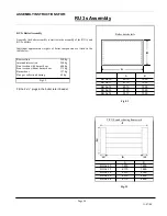
ASSEMBLY
INSTRUCTIONS
FOR:
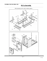
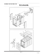
RU 1s Assembly
Содержание BRU 1 Series
Страница 16: ...ASSEMBLY INSTRUCTIONS FOR Page 16 11 07 00 ASSEMBLY INSTRUCTIONS FOR RU 1s Assembly ...
Страница 17: ...ASSEMBLY INSTRUCTIONS FOR Page 17 11 07 00 ASSEMBLY INSTRUCTIONS FOR RU 1s Assembly ...
Страница 23: ...ASSEMBLY INSTRUCTIONS FOR Page 23 11 07 00 ASSEMBLY INSTRUCTIONS FOR RU 2S BRU 2S RU 2s Assembly ...
Страница 29: ...ASSEMBLY INSTRUCTIONS FOR Page 29 11 07 00 ...