Theme Plus Issue 2.1 28/06/01
Page 7 of 12
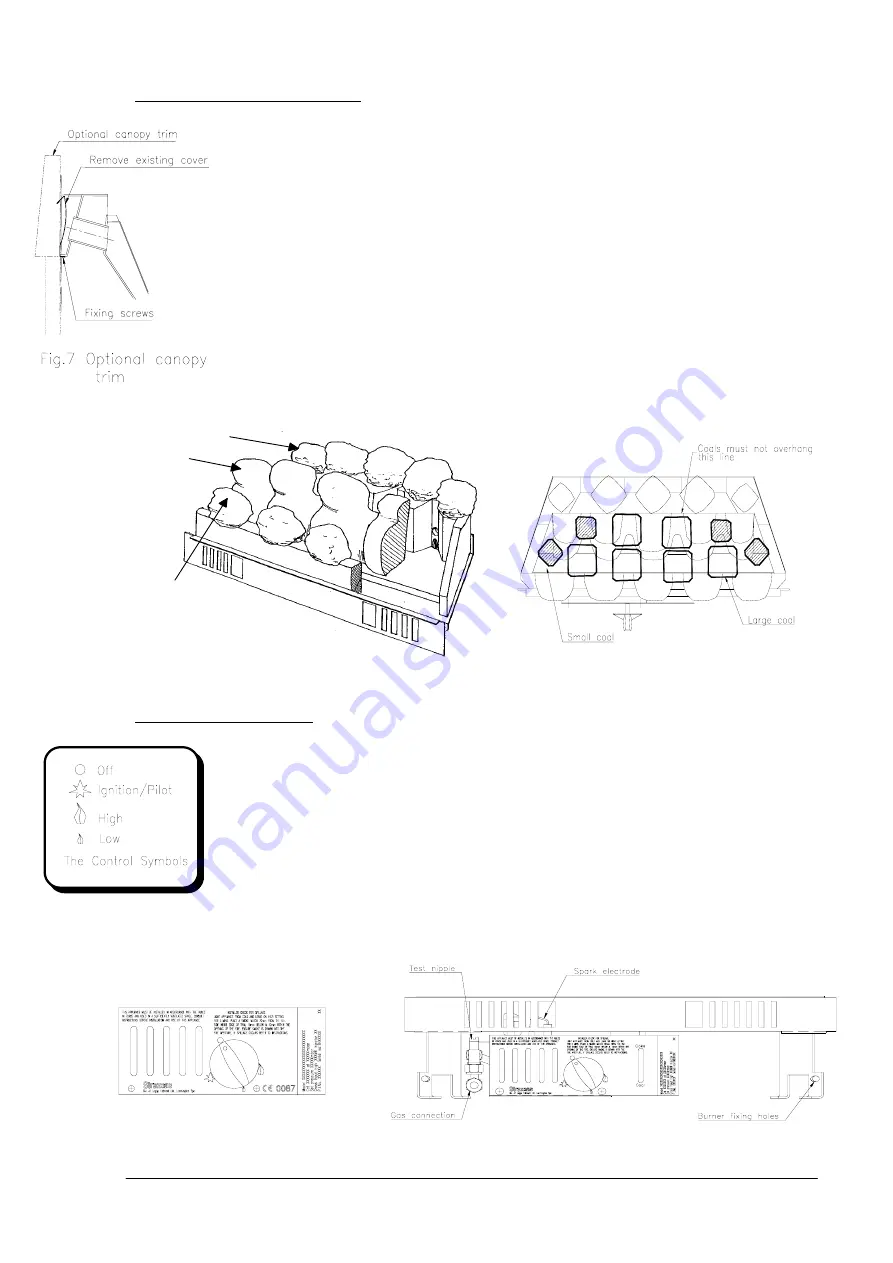
Fig. 8 The data badge plate & test
Final assembly for all types of flue
Following satisfactory installation of the convection box into the opening, proceed as follows:
1. Secure the burner to the convection box using the two screws provided, through the
holes in the front of the legs.
2. Connect the gas supply pipe to the inlet elbow.
3. The ceramic components are fragile and should be handled with care. Refer to Figs.
5 and 6 for positioning of ceramic fibre blocks and coals.
4. Place the chair shaped back ceramic on the burner, pushing it back against the
upturned edge of the burner plate.
5. Place the centre ceramic on the back ceramic pushing it back to sit comfortably
between the tapered sides.
6. Spring forward the slotted front plate and slide the front ceramics down as far as the
stops.
7. Remove the coals from the bag; note that there are 2 sizes supplied with the burner.
Place them on the ceramic blocks in accordance with Fig. 6.
8. If a flat trim or box trim has been supplied, attach it to the fire flange by means of the
magnets. If the optional canopy trim has been supplied, first remove and discard the
existing front cover by undoing the two screws in its bottom edge, then secure the
canopy trim using the same fixings. (See Fig. 7)
Note:
The flat trim and optional canopy trim cannot be used with the spacer frame.
Leak test & pressure test
1. Turn on the main gas supply and check for gas soundness.
2. Remove pressure test screw, and fit pressure gauge to pressure test point.
3. Light the fire (see next section).
4. Turn control knob anti-clockwise to
High
position.
5. When the control knob is in the
High
position, you should have a gas pressure of
19.0mbar ± 1.0mbar when using natural gas and 36.5mbar for propane.
6. Extinguish the fire by turning the control knob clockwise to the
Off
position.
7. Remove the pressure gauge and replace the pressure test screw. Check again for
gas soundness.
8. Fit the front fret by hooking the support lugs at each end over the slotted front plate
on the burner (if using a Straxgas fret), or place an alternative front fret in front of the
burner.
Note:
If a fret from another manufacturer is being used, it must comply with the minimum free
area requirements of Fig. 1.
Fig.6 Placing the loose coals
Back ceram ic
Centre ceram ic
Front ceram ic
Fig.5 Assembling the ceramic blocks
Fig.9 Data badge plate - propane version


