Theme Plus Issue 2.1 28/06/01
Page 10 of 12
Replacement of parts
Before commencing any servicing always ensure that the fire is isolated from the gas supply
and that the fire is cold. After servicing always check for gas soundness.
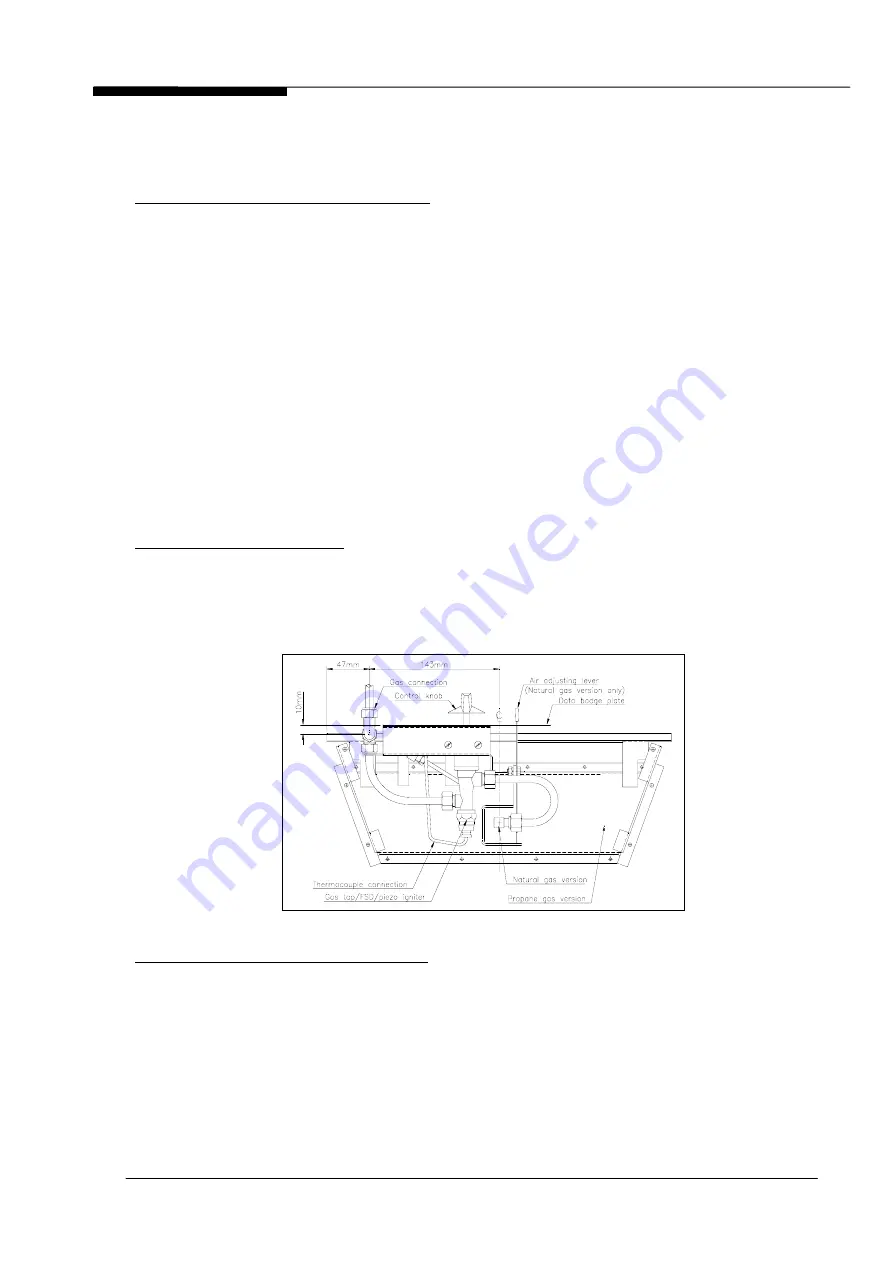
Replacement of gas tap/FSD/piezo igniter
1. Turn off the gas supply by isolation cock.
2. Lift off the front fret and remove the coals and ceramic blocks.
3. Remove 2 screws holding burner to box.
4. Undo multidirectional gas connection.
5. Remove burner from the appliance.
6. Pull off control knob.
7. Remove the 2 screws securing the Data Badge plate and remove the plate.
8. Disconnect ignition lead to the igniter unit.
9. Disconnect all 3 gas connections to gas valve as well as the connection to the
thermocouple.
10. Remove 2 screws securing the valve to the mounting bracket, and discard old
tap/FSD/piezo igniter complete.
11. Assemble the new tap/FSD/piezo igniter on the mounting bracket. Ensure that the
filter is in position in the pilot outlet orifice on the tap body.
12. Reassemble the appliance in reverse order.
13. Replace the ceramic blocks and coals (see Figs. 5 and 6).
14. Turn on the gas supply and check for soundness.
Note: The igniter is not replaceable separately.
Replacement of main injector
1. Repeat operations 1 - 5, as described for 'Replacement of gas tap/FSD/piezo igniter'.
2. Remove gas pipe from gas valve to injector.
3. Unscrew injector and replace, making certain that the jet size stamping corresponds
to the specification on the Data Badge plate.
4. Reassemble in reverse order.
5. Turn on the gas supply and check for soundness.
Replacement of ignition & pilot assembly
1. Repeat operations 1 - 7, as described for 'Replacement of gas tap/FSD/piezo igniter'.
2. Disconnect
thermocouple
connection to the gas tap/FSD/piezo igniter.
3. Disconnect pipe from base of pilot burner tube.
4. Pull off connector on the base of the igniter probe.
5. Remove 2 screws on gas burner and remove ignition unit complete.
6. Fit new pilot assembly and reassemble in reverse order.
7. Turn on the gas supply and check for soundness.
8. Check operation of ignition system.
Fig. 11 Underside of burner


