SFG10E ELECTRIC SURFACE GRINDER — OPERATION AND PARTS MANUAL — REV. #1 (07/16/07) — PAGE 17
ASSEMBLY INSTRUCTIONS/OPERATIONS
against the inside of the SURFACE GRINDER frame.
The more aggressive flails require greater forces to keep
them contained on the block. These forces, in turn,
create faster and/or uneven bushing wear rates.
Because scarifier bushings are a critical component of
the actual scarifying process, it is important that each
bushing be inspected on a regular basis to determine
proper structural integrity.
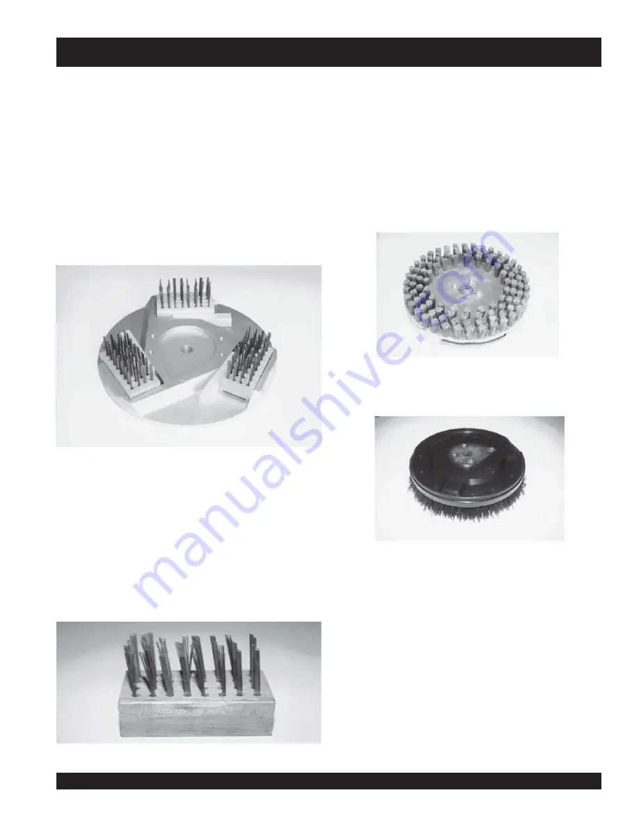
Wire brushes
Typical applications include light scarifying and cleaning of
concrete, asphalt, steel and tile surfaces. Wire brushes are
secured to the machine with plastic wedges. FIGURE 12.
Wire brushes are available in a number of flat wire sizes and
resulting configurations. With continuous use, the flat wire will
take a “set” that can limit effectiveness and overall productivity.
FIGURE 13. For best results, flat wire brushes should be rotated
end for end in the aluminum multi-accessory disc a minimum
of once for every one hour of operation. External weight applied
to the SURFACE GRINDER will not normally increase
productivity rates and only accelerate flat wire wear rates.
FIGURE 12
FIGURE 13
Floor Brushes
Eleven inch diameter, silicon carbide impregnated, floor
brushes are available in a number of styles and designs for
general maintenance and cleaning projects. FIGURE 14.
They are especially effective cleaning soiled concrete floors
with the addition of water soluble solvents. These types of
brushes are directly mounted to the multi-accessory disc
with the included 1/2 inch x 2 inch long Grade 5 capscrews.
A kidney shaped drive plate is provided on the back side of
the brush. This drive plate fits into a recess provided in the
multi-accessory disc. FIGURE 15.
FIGURE 14
FIGURE 15
SCRAPE-R-TACH® Industrial Floor Coatings Removal
System
This multi-accessory attachment is designed to remove
many urethanes, epoxies, paints, mastics and other, similar
material accumulations from concrete floor surfaces.
FIGURE 16. Each assembly utilizes two tungsten carbide
inserts set at a precise angle. The rotating inserts “cut and
shave” against the work surface material with a “scraping”
action that removes materials with highly productive results.
To increase the effectiveness of the inserts, the scraper
block design incorporates a Lord® type rubber mount that
helps absorb damaging shocks while allowing the inserts
to more easily follow local variations in the surface contour.
Units are secured to the machine with plastic wedges.
Содержание SFG10E
Страница 39: ...SFG10EELECTRICSURFACEGRINDER OPERATIONANDPARTSMANUAL REV 1 07 16 07 PAGE39 NOTE PAGE ...
Страница 46: ...SFG10EELECTRICSURFACEGRINDER OPERATIONANDPARTSMANUAL REV 1 07 16 07 PAGE46 WHEEL DOLLY ASSY WHEEL DOLLY ASSY ...
Страница 48: ...SFG10EELECTRICSURFACEGRINDER OPERATIONANDPARTSMANUAL REV 1 07 16 07 PAGE48 FRAME ASSY FRAME ASSY ...
Страница 52: ...SFG10EELECTRICSURFACEGRINDER OPERATIONANDPARTSMANUAL REV 1 07 16 07 PAGE52 SCARIFIER ASSY SCARIFIER ASSY ...
Страница 58: ...SFG10EELECTRICSURFACEGRINDER OPERATIONANDPARTSMANUAL REV 1 07 16 07 PAGE58 DECALS DECALS ...
Страница 61: ...SFG10EELECTRICSURFACEGRINDER OPERATIONANDPARTSMANUAL REV 1 07 16 07 PAGE61 NOTE PAGE ...


