background image

Installation

9

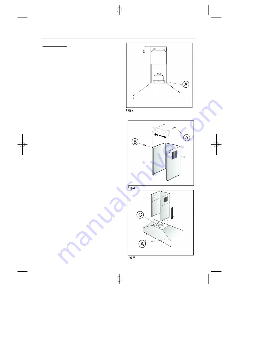
Wall fixing

(figures2,3,4)

Drill the holes A, as per the dimen-
sions in fig 2.

Using  the  screws  and  dowels
supplied with the appliance, fasten
the wall bracket to the wall.

•    Ensure that they are suitable for the

type  of  wall  where  the  cooker
hood is to be mounted.

Locate and fasten the hood to the
wall.  Secure the body of the hood
as shown in fig 4.

Secure  the  top  junction  piece  to
the wall bracket through the side
holes  using  the  screws  provided
see fig 3.

Securing the telescopic flue.  

Make  sure  the  the  power  cables
are  inside  the  decorative  flue  to
conceal them.

Make  sure  there  is  an  exhaust
opening prepared.

Adjust  the  width  of  the  support
bracket (fig 3), then fix it into the
ceiling using the screws shown in
fig 3 - A.  This should be as shown
in fig 2.

Connect  the  flange  as  per  fig  4.
Then  insert  the  two  pieces  of  the
flue.

In some cases it may be necessary
to adjust the length of one or both
of  the  chimney  sections.   Cut  the
bottom of each section so that the
cut is hidden using suitable cutting
implements.   Please take care not
to obstruct the ducting vents.

08 27123 01- 1100TRC hood  17/5/05  4:14 pm  Page 11

Содержание 1100TRC

Страница 1: ...1100TRC Chimney Hood User Installation Instructions 08 27123 01 1100TRC hood 17 5 05 4 14 pm Page 1 ...

Страница 2: ...08 27123 01 1100TRC hood 17 5 05 4 14 pm Page 2 ...

Страница 3: ...ation requirements Mounting height 6 Method 1 Re circulation 7 Method 2 Extraction through an outside wall 8 Wall fixing 9 Electrical connection 10 Frame mounting instructions 11 Technical Data 12 Customer Support 13 Please read this handbook carefully and keep it for future reference 1 Contents 08 27123 01 1100TRC hood 17 5 05 4 14 pm Page 3 ...

Страница 4: ...ntee and Service availability only apply to the UK and Republic of Ireland Installation This appliance has been designed for use as an exhausting air evacuation to the outside or filtering indoor air re cycling hood Note This appliance may be supplied fitted with carbon filter s for use as a re circulating hood If you wish to install the hood for extraction through an outside wall a compatible duc...

Страница 5: ...e grease filters motor carbon filters slider control light bulb frame Outlet adaptor inner chimney extension piece outer chimney extension piece wall bracket adjustable Figure 1 Parts Identification 08 27123 01 1100TRC hood 17 5 05 4 14 pm Page 5 ...

Страница 6: ... control to the on position To switch off return the control to the off position Important safety notes Keep hob rings covered with pans when switched on to avoid damaging the hood The use of an unprotected flame can cause a fire hazard Do not flambé food underneath the hood When frying foods take care to avoid cooking oil flares Wash the grease filters regularly refer to the cleaning section Do n...

Страница 7: ...it the clean filters Outer casing All external parts of the outer casing and visor can be safely cleaned with a clean cloth wrung out in hot soapy water Do not use caustic pastes abrasive cleaning powders wire wool and hard implements as they will damage the surfaces Carbon filters models installed for use with the re circulation method only The carbon filters absorb cooking odours and need renewi...

Страница 8: ...ich is not of the balanced flue type Mounting height The cooker hood must be fitted at least 650 mm above a gas or electric hob If cooker hob instructions give a different figure to that given above then the higher measurement should be followed To prevent possible hood cut out a clearance of 750 mm is recommended above gas hobs where possible Select method of operation The cooker hood has two pos...

Страница 9: ...en selecting the best position for the hood ensure that air flow from the air ducting vents is not obstructed by cupboards shelves etc Do not vent into enclosed cupboard space Assembly 1 Remove the grease filters 2 Fit the carbon filter if supplied may be packed separately by engaging it onto the peg in the centre of the fan grille and twisting in either direction by a quarter turn 90 until it is ...

Страница 10: ...ucting kit and connect to the ducting outlet adaptor Horizontal duct runs should be avoided A slope of 5 or more upwards from the hood to the wall outlet will assist the flow of air The ducting pipe and any connecting pieces should be coupled to the preceding piece by pushing into and never over it the upper part must be fitted over the lower part The outlet from the hood must not be ducted into a...

Страница 11: ...e fig 3 Securing the telescopic flue Make sure the the power cables are inside the decorative flue to conceal them Make sure there is an exhaust opening prepared Adjust the width of the support bracket fig 3 then fix it into the ceiling using the screws shown in fig 3 A This should be as shown in fig 2 Connect the flange as per fig 4 Then insert the two pieces of the flue In some cases it may be n...

Страница 12: ...eed as follows 1 The wire which is coloured blue must be connected to the terminal marked N neutral LOAD or coloured black 2 The wire which is coloured brown must be connected to the terminal marked L live LOAD or coloured red The fused spur socket should be positioned where is is easily accessible so you can switch off the supply to the hood when renewing the light bulb Figure 6 Typical example o...

Страница 13: ...ct C to A before fixing A to B Figure 7 2 Side frame assembly Connect the endcap E to the side bar D From inside the hood pass screw F through the specific hole Fit part B onto screw F Screw E onto B From inside the hood pass screw H through the hole and attach part G Screw part G into sidebar D Repeat on other side Re fit the 3 grease filter panels 479 mm 98 mm 1083mm 98 mm 40 mm 99 mm 99 mm A B ...

Страница 14: ... filters x 3 metal filters Motor rating 1 x 250 W Extraction Rate External Position 3 440m 3 H Position 2 378m 3 H Position 1 303m 3 H Extraction Rate Internal Position 3 301m 3 H Position 2 259m 3 H Position 1 227m 3 H Noise level External Venting Position 3 56 dBA Position 2 51 dBA Position 1 48 dBA Noise Level Internal Venting Position 3 59 dBA Position 2 56 dBA Position 1 53 dBA Co nforms with...

Страница 15: ...queue Calls are answered in strict rotation as our Customer Support Representatives become available Enter appliance numbers here for future reference Please ensure you have the above details Model No and Serial No to hand when calling Customer Support they are essential to booking your call 13 Model No Serial No Customer Support 08 27123 01 1100TRC hood 17 5 05 4 14 pm Page 15 0844 815 3740 ...

Страница 16: ...STOVES STONEY LANE PRESCOT MERSEYSIDE L35 2XW 08 27123 01 05 2005 08 27123 01 1100TRC hood 17 5 05 4 14 pm Page 16 ...

Отзывы: