Parameter description:
The following values can change the equipment characteristics
and are therefore to be set with utmost care.
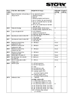
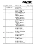
A1: Switch mode contact K1
A2: Switch mode contact K2
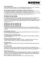
The switch mode for the relays, i.e. cooling or heating function, can be programmed independently
at works. Heating function means that the contact opens as soon as the setpoint is reached, thus
power interruption. At cooling function the contact closes, if the actual value is above the required
setpoint. (see fig. 1 + 2)
A3: Function of contact K1 at sensor error
A4: Function of contact K2 at sensor error
At sensor error the selected relay falls back into the condition pre-set here. If there is a data-loss in
parameter memory (display indicates “EP”) both contacts K1 and K2 are switched off.
A5: Selection setpoint 2 or DeltaW
This parameter determines whether the setpoints for thermostat 1 and 2 independently adjustable
(A5=0) or whether they are tied with one another via a switching offset DeltaW (A5=1). This
parameter applies only to contact K2 (see parameter P1).
A8: Display mode
The value can be indicated in integrals or with decimals in 0,5°K or 0,1°K. At indication in 0,5°K the
value is rounded up or down. In general, all parameter indications are presented in 0,1°K.
A9: Weighing factor
With this parameter the actual value can be submitted to weighing. The measured value is
multiplied by it and both indicated in the display and applied for regulation.
A10: Indication value for lower value linear analogue input
A11: Indication value for upper value linear analogue input
Only relevant, if the controller is programmed for a voltage input (0…10V linear) or a current input
(4…20mA linear). These parameters allow scaling of the linear analogue input. The value to be
indicated for the lower and upper entrance value then defines the range the controller will indicate.
For input range 4…20mA the display will show sensor error if the input signal drops below 4mA.
A19: Parameter lock
This parameter enables locking of each parameter level. If third level is locked, only parameter A19
may be changed.
A20: Activation of key acknowledgement
This parameter permits to switch on/off the key confirmation by internal buzzer.
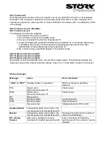
A30: Function alarm exit
The alarm exit evaluates an upper and a lower limit value (see parameters P30 and P31), whereas
a selection is possible as to whether the alarm is active if the temperature lies within these two
limits, or whether the alarm is released if the temperature lies beyond them. In the case of sensor
error, the alarm is activated independently of this adjustment. The exit can also be inverted, so that
it functions like a release (see fig. 3 – 6 at parameters P30/31).
A31: Special function at boundary or range alarm
Here can be selected whether, in the case of an alarm, the indication to flash and/or the buzzer is
to start. Sensor alarm (display F1L or F1H) is indicated independently thereof by flashing display
and the buzzer.
Содержание ST710-KHJV.03
Страница 2: ......


