

StorCase Technology, Inc.
RJR400 User’s Guide - Rev. C00
9
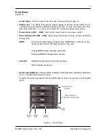
Installing the Receiving Frame
The drive should be installed into the carrier before installing the receiving frame into the
mounting bay of a computer or expansion chassis.
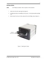
1.
Turn OFF power to computer or expansion chassis.
2.
Open computer or expansion chassis according to manufacturer’s instructions. If
necessary, temporarily remove any expansion boards that may make installation
difficult.
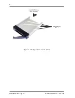
3.
With the drive carrier locked into place inside the receiving frame, install the RhinoJR
into the 5.25” drive opening in the computer or expansion chassis. Fasten into
place with the four (4) #6-32 Phillips Pan Head screws provided.
4.
Adjust the front of the receiving frame so that the carrier slides freely in and out of
the receiving frame guides. The position of adjoining peripheral units may require
adjustment.
5.
Connect the I/O cable from the host adapter to the receiving frame.
6.
Connect the DC power cable from the DC power supply in the computer or expan-
sion chassis to the power connector on the RhinoJR receiving frame rear panel.
7.
Replace any expansion boards that may have been removed earlier. Replace the
system cover according to the manufacturer’s instructions.
8.
Reconnect any system or peripheral cables removed earlier.
9.
Turn ON power to the computer. If the installation was successful, and all cables
have been properly attached, the system should boot normally.


