
DE100i-A100 User's Guide - Rev. C02
StorCase Technology, Inc.
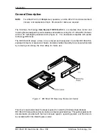
Introduction
5
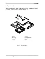
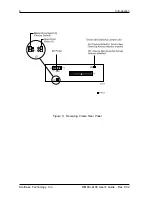
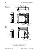
Receiving Frame Rear Panel
(Figure 5)
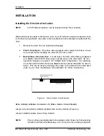
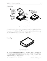
DC Power Connector (J3):
The DE100i-A100 uses a standard 4-pin DC Power
Connector to accept DC power.
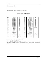
I/O Connector (J2):
The input/output connector provides a standard interface for
all IDE signals. See Table 3 on page 13 for J2 pin assignments.
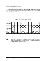
Master/Slave Selection Jumper
(J5):
Master Drive configuration (default).
Forces master drive configuration on receiving frame. Change jumper to set slave
drive configuration. Refer to Table 1 on page 12 for further information.
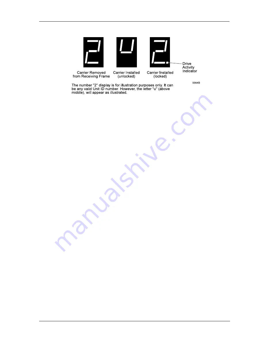
Device Spin Down/Up Timer Jumper (J6):
Jumper installed (Factory Default)
enables device spin down/up visual indicator. Receiving frame unit ID number
display (Figure 4) will flash to indicate device spin down/up.
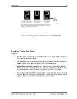
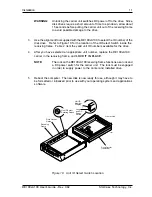
Figure 4: Receiving Frame Unit ID Number and Activity Display
Содержание Data Express DE100i-A100
Страница 1: ...StorCase Technology Data Express DE100i A100 Removable Ultra ATA133 Drive Enclosure User sGuide...
Страница 13: ...StorCase Technology Inc DE100i A100 User s Guide Rev C02 6 Introduction Figure 5 Receiving Frame Rear Panel...
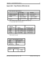
Страница 21: ...StorCase Technology Inc DE100i A100 User s Guide Rev C02 14 Appendix A Specifications Dimensions APPENDICES...


