


S/AI
Page 36 of 52
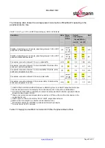
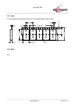
6.3 Re-flow Temperature-Time Profile
The data here is given only for guidance on solder and has to be adapted to your process and
other re-flow parameters for example the used solder paste. The paste manufacturer provides a re-
flow profile recommendation for his product.
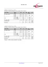
Figure 16: Soldering Temperature-Time Profile (For Reflow Soldering)
Preheat
Main Heat
Peak
tsmax
tLmax
tpmax
Temperature
Time
Temperature
Time
Temperature
Time
[°C]
[sec]
[°C]
[sec]
[°C]
[sec]
150
100
217
90
260
10
230
50
Average ramp-up rate
[°C / sec]
3
Average ramp-down rate
[°C / sec]
6
Max. Time 25°C to Peak
Temperature
[min.]
8
Opposite side re-flow is prohibited due to module weight.
Devices will withstand the specified profile and will withstand up to 1 re-flows to a maximum
temperature of 260°C. The reflow soldering profile may only be applied if the S resides
on the PCB side looking up. Heat above the solder eutectic point while the S is mounted
facing down may damage the module permanently.


