background image

19

3.14 EXTENDED STORAGE

Refer to the following steps for storage of the freezer
over any long period of shutdown time:

A. Turn both FREEZING CYLINDER OFF-ON switches

to the OFF position.

B. Disconnect (unplug) from the electrical supply

source.

C. Clean thoroughly with a warm water detergent all

parts that come in contact with the mix. Rinse in
clear water and dry all parts. 

Do not

 sanitize.

NOTE

Do not let the cleaning solution stand in the
hopper or in the freezer barrel during the
shutdown period.

D. Remove, disassemble and clean the front door, mix

inlet regulator and auger parts. Place the auger
flights in a plastic bag with a moist paper towel to
prevent them from becoming brittle.

E. On water cooled freezers, shut off and disconnect

water supply at rear of freezer; run compressor for
2-3 minutes to open water valve, and blow out all
water first through inlet then outlet line, using air or
carbon dioxide.

3.15 PRODUCT CONSISTENCY ADJUSTMENT

The freezer's control system monitors the consistency
(firmness) of the product (mix) in each freezing cylinder.
The program module senses the consistency of the
product and shuts off the drive motor and refrigeration
system when the pre-programmed consistency is reached.
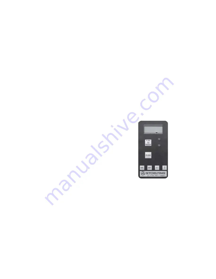
The control panels on the front of the freezer allow the
operator to adjust each freezing cylinder to create the
desired product consistency.

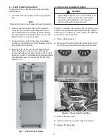
A. Place the FREEZING CYLINDER OFF/ON switch in the

ON position.

B. Press the SET button on the Control Panel once.

Fine Adj  will appear on the LCD screen (Fig. 30).

C. Press the up arrow button 

(⇑) 

(⇑) 

(⇑) 

(⇑) 

(⇑) 

until the desired consis-

tency setting is displayed. The higher the number, the
greater the product consistency. The control may be set
from 1 to 9. Each time the up arrow

  (⇑) 

(⇑) 

(⇑) 

(⇑) 

(⇑) 

button is

pressed, the value will increase by 1 until the value
reaches 9, then restart at 0. The 0 setting cannot be set.

D. Press the SET button once to save the setting change

and return to the current mode display.

Figure 30. Product Conststency Control

Fine Adj

1-9     5

3.16  LOCKING OUT CONTROL PANEL

The IntelliTec control has a tamper proof mode to prevent
unauthorized use. When set, all buttons on the control
panel are disabled. To lock out the control panel:

A. Press and hold the PUSH TO FREEZE button for 5

seconds.

B. While still holding the PUSH TO FREEZE button, press

the CLEAN button once.

 C. Release both buttons. An astrisk (*) will apear after the

word MODE on the display, indicating that the control
is in the lock out mode.

D. To unlock the control panel, repeat steps A, B and C.

Содержание Futura F144I

Страница 1: ...Futura F144I OWNER S MANUAL Manual No 513608 April 2005...

Страница 2: ......

Страница 3: ...are certified in the Stoelting Technicare program Model No _______________________ Serial No _______________________ Purchase Date ____________________ Start Up Date ____________________ CALL Distrib...

Страница 4: ......

Страница 5: ...new parts for freezers built prior to date of change DO NOT ATTEMPT to operate the freezer until instructions and safety precautions in this manual are read completely and are thoroughly understood If...

Страница 6: ......

Страница 7: ...light specific safety information the following safety definitions are provided to assist the reader The purpose of safety symbols is to attract your attention to possible dangers The safety symbols a...

Страница 8: ......

Страница 9: ...g 9 3 4 Freeze Down and Operation 10 3 5 Mix Information 11 3 6 Removing Mix from Freezer 11 3 7 Cleaning the Freezer 12 3 8 Disassembly of Freezer Parts 12 3 9 Cleaning the Freezer Parts 14 3 10 Sani...

Страница 10: ...tizingAgitator Shaft 10 15 Dispensing Product 11 16 Removing Mix Inlet Regulator 11 17 Draining Mix 12 18 CleaningAgitator Shaft 12 19 Auger Flight Wear and Front Auger Support Wear 13 20 Removing Fro...

Страница 11: ...akes or smoothies from the right spigot with the conve nience and cost of one unit The freezer is designed to be usedwithbothbarrelsinoperation Ifyoudesiretouseone barrel only the freezer must be clea...

Страница 12: ...s 20 Amp maximum fuse or circuit breakers NEMA 6 20P power cord provided Automatic safeguard circuit built into electronic control protects major freezer components under normal operating conditions R...

Страница 13: ...intain a safe working environment The labels have been designed to withstand washing and cleaning All labels must remain legible for the life of the freezer Fig 3 Warning Label Locations Labels should...

Страница 14: ...is necessary level the freezer by turning the bottom part of each leg in or out Then separate freezer base gasket and install with the seam to the back and the flat to the bottom C Air cooled freezers...

Страница 15: ...front of the freezer to the door end of the stand Secure the freezer to the stand with the nuts and lock washers provided Then separate freezer base gasket and install the seam to the back and the fl...

Страница 16: ...6...

Страница 17: ...ve noise or vibration occurs SECTION 3 INITIAL SET UP AND OPERATION 3 2 OPERATION CONTROLS AND INDICATORS Before operating the freezer it is required that the operator know the function of each operat...

Страница 18: ...and place the Freez ing Cylinder Off On switch to the ON position Refer to Troubleshooting in Section 4 H Green Light The green light is used to indicate that the product has reached the proper consi...

Страница 19: ...OW speed position The HIGH speed position is used to blend fruit into dairy mix when making smoothies The LOW speed position is used during cleaning procedures Figure 11 Mix Inlet Regulator 3 3 SANITI...

Страница 20: ...or O ring or check if the mix inlet regulator was installed correctly or that the freezer is level F Place the FREEZING CYLINDER OFF ON switch in the ON position then press the PUSH TO FREEZE swtich u...

Страница 21: ...e used in place of cleaning and sani tizing Frequency of cleaning and sanitizing is determined by Federal State and local regula tory agencies Figure 15 Dispensing Product 3 5 MIX INFORMATION Mix can...

Страница 22: ...container under the spigot to catch the water When the water has drained turn the FREEZING CYLINDER OFF ON switch to the OFF position Allow the freezer barrel to drain completely CAUTION Hazardous Mo...

Страница 23: ...the studs Fig 20 Figure 20 Removing Front Door C Remove the rosette caps from the front door Push the spigot body through the bottom of the front door and remove Fig 21 Figure 21 Front Door Disassemb...

Страница 24: ...3 11 ASSEMBLY OF FREEZER To assemble the freezer parts refer to the following steps NOTE Petrol Gel sanitary lubricant or equivalent must be used when lubrication of parts is specified NOTE The Unite...

Страница 25: ...to the surface of the cam on the spigot handle prior to assembly of handle to the spigot body H Install the spigot bodies with O rings into the front door from the bottom Fig 26 Push straight up until...

Страница 26: ...g efforts within a layer of soil material milkstone Thorough cleaningproceduresthatinvolvemilkstone removal are critical for operators of frozen dessertmachines SANITIZING Kills bacteria Can be effect...

Страница 27: ...the ability to remove milkstone Milkstone will become a problem if not remedied with additional products and procedures THE USE OF CHLORINE TEST STRIPS Test strips are used to determine concentration...

Страница 28: ...eriodic cleaning To clean refer to the following procedures 1 Remove the Phillips head screw from the bottom of the right side panel and then slide the panels down and out 2 To remove the condenser fi...

Страница 29: ...he drive motor and refrigeration systemwhenthepre programmedconsistencyisreached The control panels on the front of the freezer allow the operator to adjust each freezing cylinder to create the desire...

Страница 30: ...20...

Страница 31: ...ing cylinder Check the mix level on the affected freezing cylinder If the level mix is low add mix Look for ice crystals in the liquid mix in the hopper Ice crystals can clog the mix inlet regulator a...

Страница 32: ...ORCONDITIONCODE12 If the control panel displays a left hopper sensor error Error Code 12 place the Freezing Cylinder Off On Switch in the Off position wait 10 seconds and return the switch to the On p...

Страница 33: ...d s i r e s n e d n o C 4 t f o s o o t g n i t t e s y c n e t s i s n o C 5 n e k o r b e r a x i m n i s r e z i l i b a t S 6 n w o d g n o r w d e l b m e s s a s i r e g u A 7 m e l b o r p n o...

Страница 34: ...n w o d r o t a l u g e r t e l n i x i m e c a l p e R 2 g n i r O r o t a l u g e r t e l n i x i m e c a l p e R 3 h s u r b d e z i t i n a s h t i w n a e l C 4 t c u d o r p h s e r f h t i w r...

Страница 35: ...5 5 8 ID x 1 8 CS Front Door 1 625133 4 ID x 3 16 CS O rings are drawn to Approximate Size Rear Seal 1 624678 5 1 1 8 ID x 3 16 CS Part Number Description Part Number Description 208135 Brush Nylon 16...

Страница 36: ...94255 Auger Spring 8 10 624677 5 O ring Mix Inlet Regulator and Spigot Extension 5 Pack 6 11 3170644 Front Auger Support 2 12 149003 Auger Bushing 2 13 4157968 Auger Shaft 2 14 624678 O ring Auger Sha...

Страница 37: ...es are subject to the conditions that Buyer a signs and returns to Stoelting upon installation the Checklist Warranty Registration Card for the affected equipment b gives Stoelting prompt written noti...

Отзывы: