25
1. Assuming the side and rear panels have been removed,
perform the following procedures for removing the A.X.V.
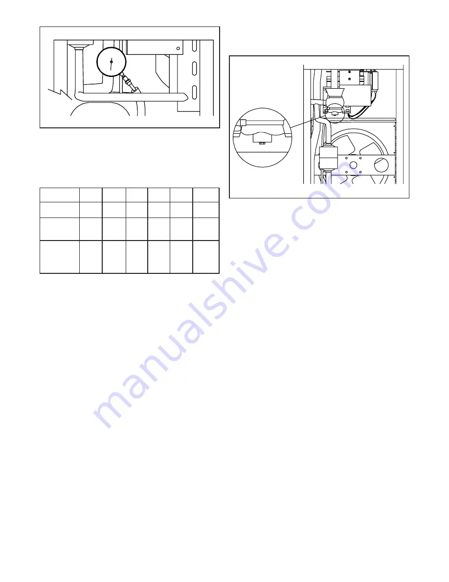
Figure 36. Adjust A.X.V.
WARNING
DISCONNECT FREEZER FROM ELECTRICAL SUPPLY
SOURCE BEFORE SERVICING.
2. Recover the refrigerant charge, then leave a port open
to prevent pressure build-up during A.X.V. removal.
3. Remove foam insulation from surrounding lines.
4. Apply a heat sink (wet cloth) to the A.X.V.
5. Unsweat the A.X.V. from its connecting lines.
6. Remove the A.X.V. with the heat sink.
C. T.X.V. Replacement
To replace the A.X.V., perform the following procedures:
CAUTION
WHEN REPLACING THE A.X.V., A HEAT SINK
(WET CLOTH) MUST BE USED TO PREVENT
DAMAGE TO THE VALVE.
1. Position the A.X.V. with heat sink, so the refrigeration
line correspond with the proper valve ports.
2. Braze lines to the A.X.V. using the appropriate brazing
material.
3. Remove the heat sink from the A.X.V.
4. Replace any foam insulation to the surrounding lines.
5. Once the A.X.V. is installed, the refrigeration system
must be purged and evacuated to 50 microns of mer-
cury for approximately 30 minutes.
Figure 35. Install Gauge
5. Pressure gauge reading should be:
6. If the pressure gauge reading does not fall within those
specifications, proceed with the following steps:
7. Remove the cap the the A.X.V. and, using a small
wrench, turn the adjusting screw 1/4 turn (90°) counter-
clockwise for more cooling or 1/4 turn (90°) clockwise
for less cooling (Fig. 36.)
8. Allow the system to level out for three to five minutes
before taking another pressure reading.
9. Should the reading still not fall within specifications,
repeat steps 8 and 9 until the correct reading is
obtained.
10.Once the correct reading is obtained, replace the cap.
Remove the pressure gauge from the Schrader valve
and replace the Schrader valve cap.
11.Replace the rear panel.
B. A.X.V. Removal
CAUTION
IF IT IS NECESSARY TO REPLACE THE A.X.V., A HEAT
SINK (WET CLOTH) MUST BE USED TO PREVENT
DAMAGE TO THE VALVE.
l
e
d
o
M
7
5
1
E
7
5
2
E
7
5
1
E
7
5
2
E
7
1
2
2
7
5
2
F
.
r
e
g
i
r
f
e
R
2
1
R
2
1
R
2
2
R
2
2
R
2
0
5
R
A
4
0
4
R
d
a
e
H
e
r
u
s
s
e
r
P
0
1
1
0
1
1
0
6
1
0
6
1
0
7
1
0
9
1
n
o
i
t
c
u
S
e
r
u
s
s
e
r
P
e
e
S
t
r
a
h
C
w
o
l
e
B
e
e
S
t
r
a
h
C
w
o
l
e
B
3
3
3
3
8
2
2
4
Содержание E157
Страница 1: ...Model E157 E257 F257 SERVICE MANUAL Manual No 513565 Rev 2 June 2003...
Страница 2: ......
Страница 4: ......
Страница 16: ...8...
Страница 28: ...20...
Страница 30: ...22...
Страница 40: ...32...
Страница 46: ...38 Figure 50 Model E157 Exploded View...
Страница 47: ...39 9 3 MODEL E157 PARTS LIST 718702 282012 SV...
Страница 48: ...40 Figure 51 Model E257 Exploded View...
Страница 49: ...41 9 4 MODEL E257 PARTS LIST 718702...
Страница 50: ...42 Figure 52 Model F257 Exploded View...
Страница 51: ...43 9 5 MODEL F257 PARTS LIST 282022 SV...
Страница 52: ...44...


