background image

1. Set Mono/Bridge switch 

Set the mono/bridge switch on the rear panel to the stereo 
position. 
When the power is on, the mono/bridge LED on the front 
panel will not light.
If the LED illuminates, you have the switch in the wrong 
position. Change the switch before continuing. 

2. Input Connections 

With the power off, connect your input source lines to 
channels 1, 2, 3 and 4. 

3. Connect Speaker Systems 

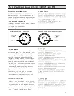
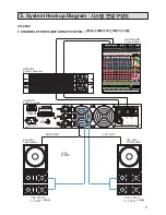
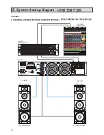
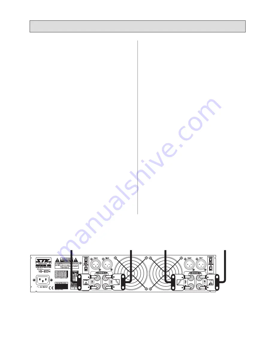
Connect speaker systems to speaker outputs as shown in 

figure 1. The total speaker load for each channel must be at 

least 4 Ohms. 

The amplifier will not operate at load conditions lower than 4 

Ohms per channel. 

4. Level Controls 

With all level controls set to 0, switch the power on. Apply 
a nominal signal to the inputs. The level of the input signal 
should be about as high as you will ever need it to be. This 

way, it will be as far above the amplifier's noise floor as 

possible, ensuring as excellent performance signal to noise 
ratio.
Adjust the input level control for each channel to achieve the 

desired maximum listening level or until the clip LED flashes 

momentarily during program peaks, whichever is lowest. 
Having set the levels in this manner will render a clean 
signal at any level as long as the clip LED is not constantly 
on. Remember, when the clip LED lights, there is distortion 

present in the amplifier's output section. 

1. 모노/브릿지 스위치 

후면부의 모노/브릿지 스위치를 스테레오 모드에 위치시킵니다. 
전원이 켜지면 모노/브릿지 표시등이 꺼져있을 것입니다. 
만약 표시등이 켜져 있다면 스위치가 잘못 위치한 것입니다. 스위
치를 올바르게 위치시켜 주십시오. 

2. 입력단자연결 

전원을 끈 상태에서 입력신호 라인들을 본 제품의 채널 1, 2, 3과 4
에 연결합니다. 

3. 스피커 연결 

그림 1 을 참고해서 스피커 시스템을 스피커 출력부에 연결해 주
십시오. 각 채널당 스피커의 합성 임피던스는 최소한 4Ω이 되어
야 합니다. 각 채널 당 로드 임피던스가 4Ω 
이하일 때에는 본 기기가 동작하지 않습니다. 

4. 음량 조절 

모든 볼륨 조절기를“0”에 놓고 전원을 켜 주십시오. 
그리고 입력 감도에 맞는 적정 수준의 입력신호를 입력하십시오. 
다음으로 본 기기의 음량조정 볼륨을 원하는 만큼 알맞게 조정하
여 주십시오. 이러한 방식은 우수한 신호 대 잡음비에 의해 앰프의 
출력을 기본 노이즈 플로어로부터 보다 우수하게 확보 할 수 있습
니다.
클립 표시등이 켜질 때까지 원하는 만큼 가장 높은 수준
까지 볼륨을 조절해 보십시오. 클립표시등이 켜지지 않게 
이러한 방식으로 볼륨을 조절하면 지속적으로 맑고 풍부한 음질
을 유지할 수 있습니다. 클립 표시등이 켜지면 앰프의 출력에 일그
러짐이 발생한 것입니다. 

4.


Connecting Your System


l


올바른 설치 방법

11

FIGURE 1. Speaker Connection Guide For Quad Operation 
그림 1. 쿼드 동작을 위한 스피커 연결 가이드 

스피커 입력

TO SPEAKER INPUT

스피커 입력

TO SPEAKER INPUT

스피커 입력

TO SPEAKER INPUT

스피커 입력

TO SPEAKER INPUT

CH1/2

CH3/4

550Wx4    /4 ohms

1100Wx2/8 ohms

(Bridged Mono)

HIGH PASS FILTER

(MONO/PARALLEL)

(MONO/PARALLEL)

PARALLEL

SHIFT

PARALLEL

SHIFT

HIGH PASS FILTER

POS(+)

NEG(-)

Содержание VS-1203

Страница 1: ...35 63 230 75 MONO PARALLEL MONO PARALLEL VS 1204 QUAD AMPLIFIER PARALLEL SHIFT PARALLEL SHIFT CH 1 CH 2 CH 3 SUB VS 2003 BI AMPLIFIER PROTECT PROTECT POWER CLIP 10 20 SIG CLIP 10 20 SIG CLIP 10 20 SIG...

Страница 2: ...5 3 Panel Description l 6 9 4 Connecting Your System l 10 18 5 System Hookup Diagram l 19 22 6 Block Diagram l 23 25 7 Specifications l 26 27 8 Warranty Information l 29 30 VS 2004 VS 1204 4 Channel P...

Страница 3: ...th variable frequency control that allow independent amplification of the full range stereo outputs and a mono bass output on a single unit The signal is then devided by active crossover filter to sep...

Страница 4: ...power company For appliances intended to operate from battery power or other sources refer to the operating instructions 8 Polarization If the appliance is equipped with a polarized alternating curren...

Страница 5: ...ols that are covered by the operating instructions as an improper adjustment of other controls may result in damage and will often require extensive work by a qualified technician to restore the appli...

Страница 6: ...itions should occur such as a short in a speaker cable or connector or excessively high operating temperatures this LED will light and the amplifier will stop operation until the condition is correcte...

Страница 7: ...ter rolls of signals below either 30Hz or 50Hz This improves bass performance by limiting sub audio cone motions making more power available for the speaker rated frequency range The filter settings f...

Страница 8: ...er is being driven past normal power limits into distortion 4 Protect Indicator LED VS 2003 VS 1203 3 VS 1 1 2 2 3 4 3 Panel Descriptions l 8 FRONT PANEL l VS 2003 VS 1203 REAR PANEL SECTION l VS 2003...

Страница 9: ...ve for weakening level of mid bass frequency range because if have double level the sub sound frequency 11 Input filter Low Cut Filter CH3 Sub The low frequency HF filter rolls of signals below either...

Страница 10: ...your power amplifier is supplied with a three conductor grounded power cord and plug connect the unit only to a properly grounded mains outlet Do not use a ground lift adapter or otherwise attempt to...

Страница 11: ...nput signal should be about as high as you will ever need it to be This way it will be as far above the amplifier s noise floor as possible ensuring as excellent performance signal to noise ratio Adju...

Страница 12: ...Speaker Outputs Connect speaker systems to speaker outputs only as shown in figure 2 The total speaker load for each bridged channel must be at least 8 ohms or above If you try to operate at less than...

Страница 13: ...VS 2004 VS 1204 3 Speaker Outputs Connect speaker systems to speaker outputs as shown in figure 3 The total speaker load for each channel must be at least 4 ohms or higher E VS 2004 VS 1204 3 1 2 VS...

Страница 14: ...ply a nominal signal to the inputs The level of the input signal should be about as high as you will ever need it to be This way it will be as far above the amplifier s noise floor as possible ensurin...

Страница 15: ...inal to the red connector of output Connect the CH 4 speaker s negative terminal to the black connector of output Note that the speaker load impedance must be 4 ohms or greater Connection For Bridged...

Страница 16: ...r 45 clockwise to lock it in place Output Connection Table l Output Function l Connector l Pins l Left CH 1 1 1 Right CH 2 1 1 Sub Mono CH 3 1 1 Connection for Stereo 2 Way Sub woofer Operation Connec...

Страница 17: ...from the AC power source before making any connections When connecting your speakers using either method be sure to pay close attention to proper polarity Although connecting your speaker systems out...

Страница 18: ...rrectly for the mode of operation you wish to use before powering up the amplifier 3 Parallel LED VS 2004 VS 1204 ONLY The parallel LED will light when you have set the rear panel switch to the parall...

Страница 19: ...5 0 15 15 0 15 15 0 15 15 0 OL 10 0 20 15 15 0 15 15 0 15 15 0 15 15 0 OL 10 0 20 15 15 0 15 15 0 15 15 0 15 15 0 OL 10 0 20 15 15 0 15 15 0 15 15 0 15 15 0 OL 10 0 20 15 15 0 15 15 0 15 0 15 15 0 OL...

Страница 20: ...0 OL 10 0 20 15 15 0 15 15 0 15 15 0 15 15 0 OL 10 0 20 15 15 0 15 15 0 15 15 0 15 15 0 OL 10 0 20 15 15 0 15 15 0 15 15 0 15 15 0 OL 10 0 20 15 15 0 15 15 0 15 0 15 15 0 OL 10 0 20 15 15 0 15 15 0 1...

Страница 21: ...5 0 15 15 0 15 15 0 OL 10 0 20 15 15 0 15 15 0 15 15 0 15 15 0 OL 10 0 20 15 15 0 15 15 0 15 15 0 15 15 0 OL 10 0 20 15 15 0 15 15 0 15 15 0 15 15 0 OL 10 0 20 15 15 0 15 15 0 15 15 0 15 15 0 OL 10 0...

Страница 22: ...5 0 15 15 0 OL 10 0 20 15 15 0 15 15 0 15 15 0 15 15 0 OL 10 0 20 15 15 0 15 15 0 15 15 0 15 15 0 OL 10 0 20 15 15 0 15 15 0 15 15 0 15 15 0 OL 10 0 20 15 15 0 15 15 0 15 15 0 15 15 0 OL 10 0 20 15 15...

Страница 23: ...23 6 Block Diagram l VS 2004 VS 1204 VS 2003 VS 1203 SMPS BLOCK...

Страница 24: ...CURRENT SPLITTER CURRENT SPLITTER CURRENT SPLITTER CURRENT SPLITTER AB AB AB AB CH 1 OUTPUT CH 2 OUTPUT BRIDGE 1 OUTPUT CH 3 OUTPUT CH 4 OUTPUT BRIDGE 2 OUTPUT HI FREQ RECTIFIERS ST BY 15V SWICH MUTE...

Страница 25: ...ONTRL DC FAULT DETECTOR CH 1 CH 2 CH 3 FROM CURRENT SPLITTER TO CURRENT SPLITTER THERMAL BIAS SENSING MUTE CONTROL CURRENT SPLITTER CURRENT SPLITTER CURRENT SPLITTER POSITIVE STEP POSITIVE STEP AB CLA...

Страница 26: ...Signal To Noise Ratio l A weighted RMS 100 Residual Noise l LPF level minimum 68 69 Damping Factor 8 50 l 300 Slew Rate 8 1 Rated Output l 52 V sec 40 4V usec Channel Separation 8 1 Rated Output l 65...

Страница 27: ...th 3 Roll Off by Filter On l CH 1 2 60 or 90 30 CH 3 20 250 Signal To Noise Ratio l A weighted RMS 100 Residual Noise l LPF level minimum 68 Damping Factor 8 50 l CH 1 2 300 CH 3 350 Slew Rate 8 1 Rat...

Страница 28: ...Note 28...

Страница 29: ...ARRANTY STK electronics are warranted to be free from defects in materials and workmanship under normal use for a period of 1 year from date of original purchase During that period STK will at its opt...

Страница 30: ...8 1 STK 1 AS STK STK STK Professional Audio A S 30 FOR YOUR RECORDS 1 STK 250 2 TEL 032 525 1788 1790 FAX 032 525 1784 E mail stkcom stkpro com www stkpro com...

Страница 31: ......

Страница 32: ...Owner s Manual for The STK VS series 2 Channel Power Amplifier Printed In Korea STK Professional Audio DEC 2013...

Отзывы: