background image

[email protected] 

|


P 651.454.5112 

|


F 651.454.5143 

|

 www.stinar.com

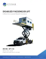
DISABLED PASSENGER LIFT

O P E R AT I O N   &   M A I N T E N A N C E   M A N UA L

MODEL: DPT-512 

S E R I A L   N O :   2 5 7 81
M A N U FAC T U R E   DAT E :   0 9/ 2 0 21

REV.02.2022

Содержание 25781

Страница 1: ...stinar com P 651 454 5112 F 651 454 5143 www stinar com DISABLED PASSENGER LIFT O PE R AT I O N M A I N T E NAN CE M AN UAL MODEL DPT 512 SE R I AL N O 2 5781 M AN U FACT U RE DAT E 0 9 2 0 21 REV 02...

Страница 2: ...tion 76 October 2021 Section 4 1 77 October 2021 Section 4 2 78 October 2021 Parts Order Form 79 October 2021 FIGURES Disabled Passenger Transporter Model DPT 512 80 83 October 2021 Electrical System...

Страница 3: ...er Control Switch 27 1 1 11 2 Intercom 27 Figure 1 1 11 Electrical System Schematic Page 1 of 4 28 Figure 1 1 11 Electrical System Schematic Page 2 of 4 29 Figure 1 1 11 Electrical System Schematic Pa...

Страница 4: ...1 3 5 Power Lift Gate 49 1 3 6 Mini Split Unit 49 SECTION 2 SERVICING THE HIGH LIFT TRUCK 50 2 1 Servicing 51 2 1 1 Use of Maintenance Stops 51 2 1 2 Truck Chassis Cab 51 2 1 2 1 General Engine Chassi...

Страница 5: ...g Air from Hydraulic Lines 73 Figure 2 3 1 Hydraulic Component Group 74 2 3 4 Hydraulic Pressure Switch Adjustment 75 SECTION 3 OVERHAUL 76 3 1 Truck Chassis cab 76 SECTION 4 PARTS LIST 77 4 1 Manufac...

Страница 6: ...2 97 Figure 4 2 6 Van body Interior Page 2 of 2 98 Figure 4 2 7 Rear Stabilizer Assembly 100 Figure 4 2 8 Front Stabilizer Assembly 102 Figure 4 2 10 Electrical Box Interior 105 Figure 4 2 11 Cab Cont...

Страница 7: ...tructions Includes a unit description recommended procedures for operation plus specifications and capabilities Section 2 Servicing The High Lift Truck Provides unit maintenance information service an...

Страница 8: ...maintenance instructions will help the operator and others avoid accident involvement NOTE The word NOTE is used to denote something that can cause minor machine damage or poor performance if ignored...

Страница 9: ...procedure may result in transmission damage Please check the manufacturer s recommendations before towing your unit These procedures are suggested general operating procedures For specific aircraft se...

Страница 10: ...ydraulic oil level and fill tank to the proper level with all hydraulic actuating cylinders fully retracted Otherwise damage may occur to the tank when the system is operated Your safety and the safet...

Страница 11: ...ctions only when the PTO is turned on from the cab control station The van lights the controls and the linear actuator on the front platform are all run off the truck s 12 VDC electrical system A hand...

Страница 12: ...Disabled Passenger Lift DPT 512 12 FIGURE 1 1 1 DISABLED PASSENGER TRANSPORTER MODEL DPT 512...

Страница 13: ...Disabled Passenger Lift DPT 512 13 FIGURE 1 1 1 DISABLED PASSENGER TRANSPORTER MODEL DPT 512...

Страница 14: ...the body to be raised vertically while the van body floor remains parallel to the ground The double scissors design is constructed of 8 x 3 203 mm x 76 mm reinforced steel tubing All pivot points are...

Страница 15: ...n this chapter for an illustration and description of this control station Van Interior Lights 4 incandescent light fixtures 2 mounted on each side are located on the van ceiling These interior lights...

Страница 16: ...e railings on the sides of the platform are painted in safety yellow The floor is constructed from diamond plate flooring 1 1 6 Screen Guard The screen guard behind the truck provides support for the...

Страница 17: ...a lift up down control switch for raising and lowering the lift gate 1 1 8 Generator Set and Related Components This disabled passenger transporter is equipped with wiring for an engine powered gener...

Страница 18: ...ILTER GAUGE CONTROL PRESSURE VALVES LOCK SWITCH STABILIZERS FLOW VALVES LOCK LIFT CYL 19 5 6 15 13 14 12 22 10 11 3 2 4 1 17 18 16 3 7 POWER PACK OPTIONAL EMERGENCY PUMP L FRONT R FRONT L REAR R REAR...

Страница 19: ...h stainless steel element Gate Valves Gate valves are located at the outlet and return ports of the hydraulic oil reservoir These valves must be kept open during normal operation Hydraulic Pump The hy...

Страница 20: ...e Stabilizer Hydraulic Cylinders Each of the four stabilizers is double acting single stage type They extend retract and hold the stabilizer legs in place Hydraulic Pressure Switch A hydraulic pressur...

Страница 21: ...ring when used with the manual override on the directional control valve Flow Control Valve A flow control valve is located in the line between the directional control valve and the lift cylinders The...

Страница 22: ...Disabled Passenger Lift DPT 512 22 FIGURE 1 1 10 HYDRAULIC COMPONENT GROUP...

Страница 23: ...his fuse provides overload protection to the Stinar installed circuits connected to the truck s HOSAR Hot On Start And Run circuit This 10 amp fuse is located inside a fuse holder mounted under the da...

Страница 24: ...lights are mounted on the rear edge of the van roof to illuminate the rear platform and stairs during night operations These lights are controlled by the toggle switches in the van body and in the cab...

Страница 25: ...ly when the parking brake is set Truck Chassis and Stabilizers Back up Alarm This alarm sounds whenever the vehicle is being driven in reverse or the van body or stabilizers are being lowered Limit Sw...

Страница 26: ...ydraulic cylinders It is actuated by either the body down switch in the cab or the body down switch in the van body front control station Solenoid Stabilizers Up This solenoid on the stabilizer spool...

Страница 27: ...ct switch is located on the right side of the lift gate It controls the tailgate down indicator in the cab It also prevents driving the truck unless the tailgate is raised 1 1 11 1 Master Control Swit...

Страница 28: ...WT BK BU 7 1 TC 2 BU TC3 FAN ROOF FAN 1 2 3 4 4 17 16 19 18 30 22 5 20 31 15 15 15 15 15 14 12 13 25 26 5 28 29 6 4 21 4 35 2 15 BK YL EMERGENCY POWER 30A RD10 55 56 OEM WT OR BK BN BU BODY POS SWITCH...

Страница 29: ...O GN BK 3 10 STAB PRESSURE SW 41 6 6 6 6 6 6 6 BN 39 3 22 OEM GY BN WT BK OR WT YL RELAY 1 RELAY 2 CONTROL TRANSFER GN BU 2 22 K 11 WT 12 WT YL 49 3 3 50 4 44 4 6 45 40 46 47 47 37 38 47 47 48 36 5 RD...

Страница 30: ...LOCATED IN HYDRAULIC CONTROL BOX 64 M POWER PACK SOLENOID CB RD 2GA RD 1 0 RD 1 0 RD 4 GENERATOR STARTER LIFTGATE BK 1 0 GROUND IN HYDRAULIC BOX 150A CB 90A 2 BATT A 1 RD 4 63 62 VAN EMERGENCY POWER A...

Страница 31: ...Disabled Passenger Lift DPT 512 31 FIGURE 1 1 11 ELECTRICAL SYSTEM SCHEMATIC PAGE 4 OF 4 RD 1 0 LIFTGATE 12 4 WIRED TO REAR OF 250V 30A PLUG SPLIT UNIT SOOW GENERATOR SET L1 L2 12 4...

Страница 32: ...tabilizers control switch This up down toggle switch is used to extend lower and raise retract the stabilizer legs Holding it in either the up or the down position engages the hydraulic pump Stabilize...

Страница 33: ...Disabled Passenger Lift DPT 512 33 FIGURE 1 2 1 1 CAB CONTROLS AND INDICATORS...

Страница 34: ...Stabilizer set indicator When lit this green light indicates that the stabilizers are fully extended and pressurized Body up down toggle switch When placed and held in the up position this switch eng...

Страница 35: ...t in severe injury 1 2 1 4 Rear Control Box The pendant mounted control switch box for the rear lift gate is located on the left side of the lift gate It contains the following controls COMPONENT DESC...

Страница 36: ...Disabled Passenger Lift DPT 512 36 FIGURE 1 2 1 3 VAN BODY CONTROL STATION...

Страница 37: ...1 Body Emergency Lowering Lever An emergency release handle for the lift cylinder lock valves is located between the cab and the left front stabilizer This handle is used along with a manual override...

Страница 38: ...Disabled Passenger Lift DPT 512 38 FIGURE 1 2 1 7 EMERGENCY OPERATING CONTROLS...

Страница 39: ...orm floodlights and van interior lights for proper operation 6 Inspect chassis cab in accordance with the guidelines of your airline 7 Check lights horn mirrors wipers safety belt and all other safety...

Страница 40: ...arking brake engaged and transmission in park Turn the PTO on Place cab stabilizers control switch Figure 1 in down position and hold until stabilizer legs are fully extended The red stabilizers down...

Страница 41: ...switch move the platform up so that it is completely out of the travel locks 2 Using the open close toggle switch hold the switch to open and up at the same time 3 This will open the lift gate 4 To lo...

Страница 42: ...nerator set Operate heating unit as follows 1 Make sure the selector switch on the heater is in the off position 2 Start generator set engine following procedures above 3 Turn thermostat to the desire...

Страница 43: ...for good visibility 3 If heating van body is required start generator set Switch on heater as needed 4 Unfold rear lift gate platform to a horizontal position See previous instructions 5 Lower rear li...

Страница 44: ...rocedures 1 2 5 1 Emergency Shutdown Procedure In case of emergency the unit may be shut down by using the stop switch on the van body control station Figure 1 2 1 3 To operate system stop switch 1 En...

Страница 45: ...nward to release the valve 2 Locate hand pump adjacent to directional control valve Place extension handle on hand pump Pump hand pump repeatedly until all stabilizer legs are fully retracted 3 After...

Страница 46: ...ll Width 102 in 2591 mm Overall Height Van Body Lowered Van Body Raised 158 in 4013 mm 306 in 7772 mm Overall Platform Height Lowered Raised 90 in 2286 mm 228 in 5791 mm Van Body Floor Height Van Body...

Страница 47: ...er tires 225 70R x 19 5G dual Inflation Pressure Cold Front Rear 110 psi 110 psi Rims 19 5 x 6 0 Fuel Tank Capacity Diesel 28 U S gal 106 liter Engine Manufacturer Ford Type Gas V10 Displacement 6 8 L...

Страница 48: ...e 60 1 8 in 1524 mm Bore 5 1 2 in 140 mm Closed Length 32 in 813 mm Extended Length 92 1 8 in 2340 mm Hydraulic Cylinder Stabilizers 4 Type Single stage double acting Stroke 16 in 406 mm Bore 5 in 127...

Страница 49: ...PROCEDURES 1 3 5 Power Lift Gate Manufacturer Dhollandia modified by STINAR Model MDL 20 Stinar Maximum Load Capacity Hydraulic Oil Type Serial 2000 lb 907 kg Chevron Rykon AW32 1 3 6 Mini Split Unit...

Страница 50: ...are recommended by the manufacturer and are intended to assist service personnel in developing their own service schedules based on their specific environment No special tools are required other than...

Страница 51: ...eed as follows 1 Raise van body to a height of about 10 feet above the ground 2 Place maintenance stops into position in work stop holders on subframes 3 Lower van body until rollers rest securely aga...

Страница 52: ...assembly The relief valve is factory set at approximately 1900 psi 131 bar The only time this valve needs adjustment is if the hydraulic pressure becomes inadequate to raise and lower the platform lif...

Страница 53: ...d Limit Switches Check control switches for operation security and cleanliness Check limit switches for freedom of movement Check actuating arms for distortion security and function Check security of...

Страница 54: ...Check hydraulic fittings for leaks and tighten or replace as necessary 50 hours Check visually Check all hydraulic hoses for cracks cuts abrasions or deterioration Replace as required 50 hours Check v...

Страница 55: ...components See Section 3 for procedure Replace burned out light bulbs or fluorescent tubes Lights are burned out Service rear lift gate generator set or heating air conditioning unit As required 2 1...

Страница 56: ...each Weekly Lithium grease Lower roller 2 1 fitting each Weekly Lithium grease Lift cylinder upper mount 1 fitting per cylinder Weekly Lithium grease Lift cylinder lower mount 1 fitting per cylinder...

Страница 57: ...Disabled Passenger Lift DPT 512 57 FIGURE 2 1 9 3 LUBRICATION POINTS...

Страница 58: ...a specific problem The troubleshooting data provided for the electrical control system presupposes that common circuitry continuity checks will be made and that no open leads or loose connections exis...

Страница 59: ...w lift gate For all other problems consult the truck s manual Structural or Mechanical Van body will not raise Emergency body down override on directional valve is engaged Release override bolt The li...

Страница 60: ...nsufficient hydraulic oil in tank Add hydraulic oil Leaks in system Find and repair Pressure relief valve bypassing Check for obstructions Clean or replace as required Check the system pressure and ad...

Страница 61: ...Adjust or replace pressure switch See Section 3 Defective directional control valve Repair or replace valve Mechanical problem See mechanical troubleshooting Electrical problem See electrical troubles...

Страница 62: ...uctural and mechanical troubleshooting above Hand pump fails to raise stabilizers Leaks in hydraulic lines or fittings Find and repair leaks Hydraulic reservoir low or empty of fluid Fill to proper le...

Страница 63: ...ILTER GAUGE CONTROL PRESSURE VALVES LOCK SWITCH STABILIZERS FLOW VALVES LOCK LIFT CYL 19 5 6 15 13 14 12 22 10 11 3 2 4 1 17 18 16 3 7 POWER PACK OPTIONAL EMERGENCY PUMP L FRONT R FRONT L REAR R REAR...

Страница 64: ...switch Defective control valve stabilizers up solenoid Replace solenoid Cab and van stabilizers down indicators do not function properly Stabilizer limit switch es improperly adjusted or defective Adj...

Страница 65: ...witch For all other problems consult the truck s manual Truck engine cranks but does not start Lift raised and parking brake is not set Set the parking brake and restart Defective body position switch...

Страница 66: ...and check stop switch in van body Defective control valve stabilizers down solenoid Replace solenoid Defective stabilizers Replace switch control switch Stabilizer legs extend but will not retract Bo...

Страница 67: ...Hydraulic System section of this Troubleshooting table Body raises or stabilizers raise or lower too slowly or quickly Hydraulic problem See Hydraulic System Troubleshooting Van body raises but will n...

Страница 68: ...it breaker CB1 is defective Replace the circuit breaker Van front and rear flood lights do not function Relay K5 is defective Replace the relay Circuit breaker CB2 is defective Replace the circuit bre...

Страница 69: ...T BK BU 7 1 TC 2 BU TC3 FAN ROOF FAN 1 2 3 4 4 17 16 19 18 30 22 5 20 31 15 15 15 15 15 14 12 13 25 26 5 28 29 6 4 21 4 35 2 15 BK YL EMERGENCY POWER 30A RD10 55 56 OEM WT OR BK BN BU BODY POS SWITCH...

Страница 70: ...O GN BK 3 10 STAB PRESSURE SW 41 6 6 6 6 6 6 6 BN 39 3 22 OEM GY BN WT BK OR WT YL RELAY 1 RELAY 2 CONTROL TRANSFER GN BU 2 22 K 11 WT 12 WT YL 49 3 3 50 4 44 4 6 45 40 46 47 47 37 38 47 47 48 36 5 RD...

Страница 71: ...LOCATED IN HYDRAULIC CONTROL BOX 64 M POWER PACK SOLENOID CB RD 2GA RD 1 0 RD 1 0 RD 4 GENERATOR STARTER LIFTGATE BK 1 0 GROUND IN HYDRAULIC BOX 150A CB 90A 2 BATT A 1 RD 4 63 62 VAN EMERGENCY POWER A...

Страница 72: ...Disabled Passenger Lift DPT 512 72 FIGURE 2 2 2 ELECTRICAL SYSTEM SCHEMATIC PAGE 4 OF 4 RD 1 0 LIFTGATE 12 4 WIRED TO REAR OF 250V 30A PLUG SPLIT UNIT SOOW GENERATOR SET L1 L2 12 4...

Страница 73: ...e stabilizers and readjust the pressure relief until the stabilizers operate at the desired rate Record the pressure reading for future reference 5 Tighten the jam nut on the pressure relief valve 2 3...

Страница 74: ...Disabled Passenger Lift DPT 512 74 FIGURE 2 3 1 HYDRAULIC COMPONENT GROUP...

Страница 75: ...zer Adjust as follows 1 Insert a pressure gauge into the system anywhere between the control valve and the stabilizer cylinder 2 Connect an ohmmeter across the N C and common terminals 3 Remove the pr...

Страница 76: ...need for overhauling the Disabled Passenger Transporter on the basis of hours of operation or years of service Repairs should be limited to the repair of components that develop defects or show signs...

Страница 77: ...ing and identifying parts and components of the Disabled Passenger Transporter Model DPT 512 manufactured by Stinar Corporation The manufacturer identification list identifies the vendor sources by na...

Страница 78: ...Disabled Passenger Lift DPT 512 78 SECTION 4 PARTS LIST FED SUPPLY CODE MANUFACTURER V32526 Stinar LLC 500 Stinar Way Blooming Prairie MN 55917 4 1 MANUFACTURER IDENTIFICATION...

Страница 79: ...rt and that it is usually available from local sources EX standard pipe fittings 4 2 1 3 Description This column presents the complete item name required for identification and procurement and may inc...

Страница 80: ...int or copy this page and send via email fax or mail to Stinar LLC Please make sure to complete all fields Note Part Numbers and Product Illustrations are included in this Manual STINAR SERIAL NUMBER...

Страница 81: ...Disabled Passenger Lift DPT 512 81 FIGURE 4 2 1 DISABLED PASSENGER TRANSPORTER MODEL DPT 512 1 OF 2 29 30 31 20 25 27 26 4 6 13 11 35 14 36 3 8 19 11 35...

Страница 82: ...Disabled Passenger Lift DPT 512 82 FIGURE 4 2 1 DISABLED PASSENGER TRANSPORTER MODEL DPT 512 2 OF 2 23 32 9 5 21 24 28 12 16 7 17 2 34 1 38 25 18...

Страница 83: ...Fuel Cap Bracket V32526 1 14 058249 Hydraulic Tank Bracket V32526 1 15 528548 Minnimizer Bracket V32526 2 16 58252 Electrical Tray Rear Guide V32526 1 17 420026 Generator V32526 1 18 1001166 Generato...

Страница 84: ...raulic Tank V32526 1 37 509366 Fender V32526 2 38 521022 Mini Split Unit V32526 1 39 Photo Cab Controls and Indicators See Figure 4 2 11 V32526 1 40 213026 Lift Cylinder Lock Valve Assembly V32526 2 4...

Страница 85: ...BU 7 1 TC 2 BU TC3 FAN ROOF FAN 1 2 3 4 4 17 16 19 18 30 22 5 20 31 15 15 15 15 15 14 12 13 25 26 5 28 29 6 4 21 4 35 2 15 BK YL EMERGENCY POWER 30A RD10 55 56 OEM WT OR BK BN BU BODY POS SWITCH OEM W...

Страница 86: ...BK 3 10 STAB PRESSURE SW 41 6 6 6 6 6 6 6 BN 39 3 22 OEM GY BN WT BK OR WT YL RELAY 1 RELAY 2 CONTROL TRANSFER GN BU 2 22 K 11 WT 12 WT YL 49 3 3 50 4 44 4 6 45 40 46 47 47 37 38 47 47 48 36 5 RD TC2...

Страница 87: ...ED IN HYDRAULIC CONTROL BOX 64 M POWER PACK SOLENOID CB RD 2GA RD 1 0 RD 1 0 RD 4 GENERATOR STARTER LIFTGATE BK 1 0 GROUND IN HYDRAULIC BOX 150A CB 90A 2 BATT A 1 RD 4 63 62 VAN EMERGENCY POWER AUX BA...

Страница 88: ...Disabled Passenger Lift DPT 512 88 FIGURE 4 2 2 ELECTRICAL SYSTEM PAGE 4 OF 4 RD 1 0 LIFTGATE 12 4 WIRED TO REAR OF 250V 30A PLUG SPLIT UNIT SOOW GENERATOR SET L1 L2 12 4...

Страница 89: ...400122 Toggle Switch Ramp Lights See Van controls V32526 REF 17 405294 Service Floodlight Front Platform V32526 2 18 400111 Toggle Switch Deck Lights See cab controls V32526 REF 19 400131 Toggle Swit...

Страница 90: ...ee van controls V32526 REF 43 953021 Linear Actuator 24 12V V32526 1 44 400133 Rev A Pressure Switch Stabilizers V32526 1 45 400078 Limit Switch Maximum Height V32526 1 46 200076 Solenoid Coil Part of...

Страница 91: ...GAUGE CONTROL PRESSURE VALVES LOCK SWITCH STABILIZERS FLOW VALVES LOCK LIFT CYL 19 5 6 15 13 14 12 22 10 11 3 2 4 1 17 18 16 3 7 POWER PACK OPTIONAL EMERGENCY PUMP L FRONT R FRONT L REAR R REAR 2300...

Страница 92: ...ev B Hydraulic components enclosure V32526 1 9 203453 Hydraulic Pump V32526 1 10 207005 Rev A Hydraulic Hand Pump V32526 1 11 212002 Check Valve 1 2 in V32526 1 12 212001 Rev A Check Valve 3 4 in V325...

Страница 93: ...Disabled Passenger Lift DPT 512 93 FIGURE 4 2 4 SCISSORS ASSEMBLY 195 7 8 8 9 12 7 6 5 3 9 10 11 15 17 16 14 13 1 2 11 7 4 056000M...

Страница 94: ...5 056000 201 Outer Upper Scissors V32526 1 6 056000 202 Outer Lower Scissors V32526 1 7 508153 Rev B Center Shaft V32526 2 8 508151 Rev B Shaft Upper Roller V32526 1 9 508066 Rev D Roller V32526 4 10...

Страница 95: ...Disabled Passenger Lift DPT 512 95 FIGURE 4 2 5 PLATFORM ASSEMBLY 6 7 8 4X 2 3 8X 1 5 4 9...

Страница 96: ...Swivel V32526 1 2 1000861 Handrail Lateral 43 inches 1067 mm High V32526 2 3 509196 Rev D Roller Extension Platform V32526 8 4 953021 Linear Actuator 24 in V32526 1 5 055400 130 Platform Extension V32...

Страница 97: ...Disabled Passenger Lift DPT 512 97 FIGURE 4 2 6 VAN BODY INTERIOR PAGE 1 OF 2 22 18 20 3 15 16 17 11 23 19 24 21...

Страница 98: ...Disabled Passenger Lift DPT 512 98 FIGURE 4 2 6 VAN BODY INTERIOR PAGE 2 OF 2 1 3 4 6 2 5 7 9 10 14 8 PASSENGER SIDE DRIVERS SIDE 13 12...

Страница 99: ...9 1001106 3 16 Diamond Plate Flooring V32526 2 10 509544 Driver s Side Window V32526 2 11 509547 Passenger s Side Window V32526 2 12 529195 Hinged Door V32526 2 13 908109 Low Profile Door Handle V3252...

Страница 100: ...2 4 2X 6 11 4X 13 8X 12 4X 1 3 8 10 058235C 058237 Rev C Mounting Lug 4 058238 Cylinder Clamp 2 1001497 Mounting Bracket 2 058240 Rev C Frame Weldment 1 508177 Rev C Upper Pin 2 508179 Rev C Lower Pin...

Страница 101: ...th Ears V32526 2 3 058237 Rev C Mounting Lug V32526 4 4 058238 Cylinder Clamp V32526 2 5 1001497 Mounting Bracket V32526 2 6 058240 Rev C Frame Weldment V32526 1 7 508177 Rev C Upper Pin V32526 2 8 50...

Страница 102: ...isabled Passenger Lift DPT 512 102 FIGURE 4 2 8 FRONT STABILIZER ASSEMBLY 7 10 1 5 11 12 13 4 9 2 8 10 SUBFRAME 6 7 2X 10 8X 1 2X 5 2X 4 2X 9 4X 4 2X 8 2X 10 14 3 3 4X 11 4X 12 8X 13 4X 14 4X 15 2X 15...

Страница 103: ...Mounting Lug V32526 4 4 058238 Rev B Cylinder Clamp V32526 2 5 1001497 Mounting Brackets V32526 2 6 1001493 Frame Weldment V32526 1 7 508177 Upper Pin V32526 2 8 508179 Lower Pin V32526 2 9 509201 Swi...

Страница 104: ...M MFG PART DESCRIPTION VENDOR CODE QTY 4 2 9 0 50084 Emergency Lift Gate Manual Override Schematic V32526 1 207005 Rev A Hand Pump V32526 1 2 302143 Valve Ball V32526 4 3 302142 Valve Mono V32526 1 4...

Страница 105: ...14 14 21 22 19 20 22 21 20 19 16 17 18 15 16 18 17 15 22 21 20 19 16 18 17 15 10 10 12 13 11 12 13 11 9 8 7 6 9 8 7 6 10 12 13 11 9 8 7 6 15A 3 2 5 4 1 1 15A 30A 5 4 3 2 5 4 3 2 1 2 1 5 4 3 2 3 1 4 K8...

Страница 106: ...erior V32526 1 1 404156 Enclosure V32526 1 2 404129 Base Panel V32526 1 3 416009 Circuit Breaker 30 amp V32526 2 4 416006 Circuit Breaker 15 amp V32526 3 5 400106 Relay SPST 12 VDC V32526 6 6 400105 R...

Страница 107: ...Disabled Passenger Lift DPT 512 107 FIGURE 4 2 11 CAB CONTROLS AND INDICATORS...

Страница 108: ...Stabilizers SET V32526 1 4 405270 Indicator Amber Tailgate DOWN V32526 1 5 400111 Toggle Switch Body Lights ON OFF V32526 1 6 400111 Toggle Switch Rear Lights ON OFF V32526 1 7 400119 Toggle Switch V...

Страница 109: ...Disabled Passenger Lift DPT 512 109 FIGURE 4 2 12 VAN BODY CONTROL STATION...

Страница 110: ...Toggle Switch Van Up Down V32526 1 6 400122 Toggle Switch Ramp lights V32526 1 7 400131 Toggle Switch Van and rear lights V32526 2 8 400119 Toggle Switch Ramp Control V32526 1 9 405271 Indicator Gree...

Страница 111: ...Disabled Passenger Lift DPT 512 111 FIGURE 4 2 13 REAR VAN CONTROL STATION...

Страница 112: ...DPT 512 112 FIG ITEM MFG PART DESCRIPTION VENDOR CODE QTY 4 2 13 0 PHOTO Van Body Rear Control Station V32526 1 1 404113 Enclosure V32526 1 2 400111 Toggle Switch Van Lights and Rear lights V32526 2 3...

Отзывы: