Stevens AeroModel Dystraction backyard /Indoor F3A Скачать руководство пользователя страница 3


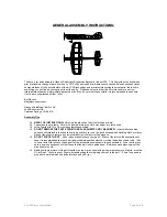
GENERAL ASSEMBLY INSTRUCTIONS: 


Thank you, for purchasing this 

Stevens Aeromodel

 Dystraction Backyard / Indoor F3A.  This kit provides the builder and 

pilot a refreshing change of pace from heavy “ARF” style plywood box airframe construction and blends stick and tissue 
design methods of the past with state of the art CAD technology and precision interlocking laser cut parts; the result is 
something you will find truly exceptional to build and fly.   Please keep in mind that this kit is intended for a novice-
intermediate builder and intermediate-advanced pilot. If you do not meet these criteria it is recommended to seek help 
from a more experienced builder / pilot.  
 
Bill Stevens 
[email protected] 
  
Stevens AeroModel 

“Built to Fly” 

4550 Beaumont Rd. 
Colorado Springs, CO 80916 
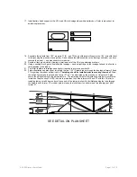
 

Assembly Tips 


‰


READ THE INSTRUCTIONS

 and review the plan sheet prior to starting any work! 

‰


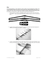
Tape plans to work table.  Cover with clear painters drop cloth, wax paper, or plastic wrap.    

‰


Join all parts with Thin CA or unless otherwise specified. 

‰


DO NOT REMOVE THE PARTS FROM THE BALSA SHEETS UNTIL REQUIRED!  

In-fact while the balsa 

parts are still retained in the sheets now is a good time to run a few good swipes with a sanding block over both 
sides of the sheet to remove any resin/residue from the laser cutting process. 


‰


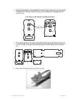
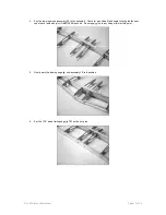
DO NOT FORCE THE FIT

 – when in doubt double check your parts – Many of the joints will be exceptionally 

snug it is recommended that each part be worked into position slowly by rocking the part back and forth.  I like 
to use a rat-tail file to knock the edge off of the interlocking components to ease assembly.  If you feel that you 
have a poor connection check first to see that the part is not upside down.  Reference each piece against the 
plan sheet or photo. 

‰


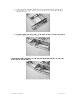
Making solid glue joints:  Hold parts together on top of plan sheet using moderate pressure to fit parts - wick thin 
CA into joint.  Hint- wrap your fingers in masking tape to avoid gluing yourself to the part!   (There is no need to 
pin parts to work table as all pieces interlock and self - jig.) 

© 2003 Stevens AeroModel.  


Page 4 of 20 

Содержание Dystraction backyard /Indoor F3A

Страница 1: ...dystraction backyard Indoor F3A 1 01 Span 24 5 Length 29 25 Area 185 Sq Weight 6 8oz 2003 Stevens AeroModel Page 1 of 20...

Страница 2: ...ed Radio Gear 1 4 5 Channel Transmitter 4ch using Y harness for ailerons 2 4 4 8g 5 4g Sub Micro Servos Cirrus 5 4g FMA PS20 E Hobby HE 2003 3 1 4 5 Ch Mini Receiver 8g 4 1 12 Servo Extension for elev...

Страница 3: ...or plastic wrap Join all parts with Thin CA or unless otherwise specified DO NOT REMOVE THE PARTS FROM THE BALSA SHEETS UNTIL REQUIRED In fact while the balsa parts are still retained in the sheets n...

Страница 4: ...fillet between the wood and the aluminum tube 2 Sand all surfaces with fine grit sand paper rounding leading edge pieces while leaving trailing edge parts square in preparation for your preferred hin...

Страница 5: ...drive EPS Drive Cut Along Etch Lines OPTIONAL GWS DRIVE SYSTEM SUPPORT IPS D LPS IPS D LPS 3 Lay one half fuselage side on a flat surface with the lettering INSIDE facing up and gently work former F2...

Страница 6: ...e fuselage sides to the former FB1 at the tail of the aircraft Friction fit the assembly check the t post to ensure that it is square to the work surface tack into position with thin CA 7 Install bals...

Страница 7: ...rmers F3 F5 I find it easiest to bow the top deck up working the front into position then the back Tack glue deck FT1 to fuselage tab and notch points Review plan sheet illustrations for more detail 1...

Страница 8: ...selage sides and FB1 Tack glue into position 12 Key FT2 into position spanning F8 F9 and Fuselage Sides 13 Key the F11 turtle deck spine into position as illustrated F11 spans F6 F7 F8 and FT2 Tack gl...

Страница 9: ...nt of the sheeting at the ply firewall F1b Stand the sheeting up along its bottom edge and tack to the fuselage sides Gently wrap sheeting to the center tack into place then run a thin bead of CA alon...

Страница 10: ...ly if required to achieve a positive fit 22 Follow illustrations on plan sheet for routing the two 1 32 ID plastic tubes through the fuselage at former F5 and F7 for guiding the rudder pull pull cable...

Страница 11: ...the pieces are in place the assembly will be pulled together straight and true 1 Build the following sub assemblies Leading Edge LE Jig from parts LE1 and LE2 Upper spar cap S3 from S3A S3B S3C Lower...

Страница 12: ...n to tack glue the spar cap at each tab notch joint IN BETWEEN each rib Do not apply glue to any rib spar joint at this point 5 Gently work the leading edge jig sub assembly LE into position 6 Key the...

Страница 13: ...ding edge trailing edge and wing tip 8 Key the leading edge cap strip LE3 into position Tack glue at each tab and notch joint then run a small amount of thin cal along the leading edge jig to cap stri...

Страница 14: ...R1 the ribs are pre notched S5 will give your covering something to adhere to when you later remove a window of film from the top and bottom of the wing between S5 and the trailing edge 11 Double eit...

Страница 15: ...g weights Minor warping may be removed with covering If for some reason you come up with a severely warped wing wet the wing with glass cleaner then re apply weights Allow assembly to dry for 24 hours...

Страница 16: ...low key parts A2 and A3 together at right angles to form the aileron leading edge Finally key the leading edge to the aileron ribs and commit your work with thin CA Follow the photo below Main Gear Fo...

Страница 17: ...Slip the 1 32 ply aileron control horn into the appropriate position on the aileron see plan sheet for details Check your orientation and think about your setscrew access if all is good secure with a...

Страница 18: ...u may find it best to make nice long takeoff runs instead of motoring into the air within a few feet Trim the plane for level flight then begin checking the responsiveness of each surface adjust to su...

Страница 19: ...THIS PAGE HAS BEEN PROVIDED TO SCHEME A COLOR SCHEME 2003 Stevens AeroModel Page 20 of 20...

Отзывы: