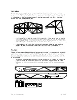
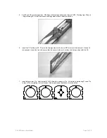
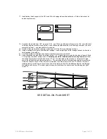
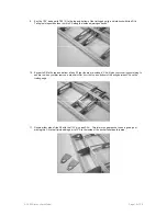


Ailerons:
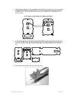
Using the rolled plan sheet as a guide, stack parts A6 1/16” Balsa, A5 1/32” Balsa, and A4 3/32” Balsa to A1 3/32” Balsa
Trailing Edge as indicated in the photo below. Friction fit. Do not glue.
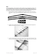
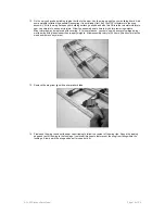
15. Continue to fill out the aileron assembly with aileron ribs A7 1/16” balsa, A8 1/16” balsa, and A9 3/32” Balsa.
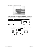
With the aileron ribs filled, out as illustrated below, key parts A2 and A3 together at right angles to form the
aileron leading edge. Finally key the leading edge to the aileron ribs and commit your work with thin CA.
Follow the photo below.
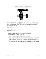
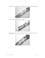
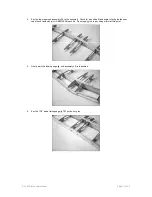
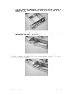
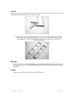
Main Gear
Follow the instructions on the plan sheet for bending and mounting the main landing gear legs from .047” music wire.
Test Fit gear legs to wing pockets.
DO NOT GLUE gear in-place until after you have covered and fit the wing to
the fuselage.
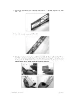
Canopy
Trim canopy along scribe line on the molded part and test fit to fuselage.
© 2003 Stevens AeroModel.
Page 17 of 20