background image

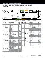
ID

Type

Pin Description

Wire Color

SW1

Address DIP

-

Node 8 - OFF-OFF-OFF-OFF -

CN2

RJ45

-

SPIKE Node Bus

n/a

CN3

RJ45

-

SPIKE Node Bus

Multi

CN4

.156" 5-Pin 

Header Node 

Power

1

Ground

BLK

2

Key

Key

3

N/C

-

4

N/C

-

5

48VDC In

GRY

CN5

.156" 4-Pin 

Header (White)

1

Switch Ground

BLK-GRN

2

8-SW-0 Switch Return

GRY-YEL

3

8-DR-0 Driver Return

ORG-YEL

4

48V Driver Power

GRY-ORG

CN6

.156" 6-Pin 

Header (White)

1

8-LP-0 Light Return

-

2

LED V+

-

3

Switch Ground

BLK-GRN

4

8-SW-4 Switch Return

GRY-WHT

5

8-DR-4 Driver Return

ORG-WHT

6

48V Driver Power

GRY-ORG

CN7

.156" 4-Pin 

Header (Black)

1

Switch Ground

BLK-GRN

2

8-SW-1 Switch

GRY-GRN

3

8-DR-1 Driver Return

ORG-GRN

4

48V Driver Power

GRY-ORG

CN8

.156" 6-Pin 

Header (Black)

1

8-LP-1 Light Return

-

2

LED V+

-

3

Switch Ground

-

4

8-SW-5

-

5

8-DR-5 Driver Return

ORG-GRY

6

48V Driver Power

GRY-ORG

CN9

.156" 4-Pin 

Header (Orange)

1

Switch Ground

BLK-GRN

2

8-SW-2 Switch

GRY-BRN

3

8-DR-2 Driver Return

YEL-ORG

4

48V Driver Power

-

CN10 .156" 6-Pin 

Header (Orange)

1

8-LP-2 Light Return

-

2

LED V+

-

3

Switch Ground

BLK-GRN

4

8-SW-6 Switch Return

GRY-VIO

5

8-DR-6 Driver Return

ORG-VIO

6

48V Driver Power

GRY-ORG

CN11 .156" 4-Pin 

Header (Green)

1

Switch Ground

BLK-GRN

2

8-SW-3 Switch

GRY-RED

3

8-DR-3 Driver Return

YEL-GRN

4

48V Driver Power

-

CN12 .156" 6-Pin 

Header (Green)

1

8-LP-3 Light Return

-

2

LED V+

-

3

Switch Ground

BLK-GRN

4

8-SW-7 Switch Return

GRY-BLU

5

8-DR-7 Driver Return

ORG-BLU

6

48V Driver Power

GRY-ORG

CN13 .100" 3-Pin 

Header

1

8-LP-4 GI Return (1A Max)

WHT-BLK

2

GI Ground

-

3

LED V+

YEL-BLK

CN14 .100" 6-Pin 

Header, Node 

Extension Bus

1

Ground

BLK 

2

DIN

VIO-BLK

3

DOUT

-

4

SCK

VIO-RED

5

RCK

VIO-ORG

6

V+ 

RED

F1

Fuse

-

7A SB, 125V

n/a

22

ELECTRONIC PINOUTS AND SCHEMATICS 

KISS PRO MANUAL 

#500-55H1-01

© 2015 KISS Catalog, Ltd. 

Under License to Epic Rights.

4.3  LOWER PLAYFIELD 48V 8-DRIVER PINOUT NODE 8 

520-6935-00

CN7

CN11

CN13

CN4

CN9

CN12

CN10

CN3

F1A

CN2

125V 7A

TIME LAG

F1B

CN5

CN8

520-6935-00
8-Driver Node

GREEN

ORANGE

NEUTRAL

BLACK

GREEN

ORANGE

NEUTRAL

BLACK

ON

1

2

3

4

CN1

CN14

CN6

TOP

Содержание KISS PRO

Страница 1: ...RES A very small percentage of people may experience a seizure when exposed to certain visual images including flashing lights or patterns Even people with no history of seizures of epilepsy may have an undiagnosed condition that can cause photosensitive epileptic seizures due to certain visual images flashing lights or patterns Symptoms can include light headedness altered vision eye or face twit...

Страница 2: ...lipper Assembly Left 36 5 11 Flipper Assembly Right 36 5 12 Sling shot Assemblies 37 5 13 Slingshot Flash Assy 02 37 5 14 Slingshot Flash Assy 04 37 5 15 Power Scoop 38 5 16 Up Post Vuk Assembly 38 5 17 Pop Bumper Assembly 39 5 18 Right Ramp Pro Assy 40 5 19 Amplifier Assembly 40 5 20 Left Ramp Assy 40 5 21 Paul Assembly Pro 40 5 22 Plastic Flash Assy 05 41 5 23 Plastic Assy 06 41 5 24 Plastic Ass...

Страница 3: ...tain the four 4 identical legs with levelers 4 DO NOT CUT STRAPPING YET Keep backbox secured in the down position 5 With the utility knife carefully cut down the left and right corners of the box 6 Let the face fall forward and remove the entire side by carefully cutting the bottom 7 With the game still in its folded position use a wrench to loos en and remove the 2 leg bolts on each side of the f...

Страница 4: ...efully raise backbox to upright position while ensuring that cables are not pinched 26 Use the wrench to Install the two 2 backbox bolts to secure the backbox as indicated on the back of the cabinet 29 Remove the playfield glass by sliding it toward you and carefully place it in a safe location Remove all playfield shipping tie downs shipping blocks and packing foam and follow any game specific un...

Страница 5: ...all the correct number of pinballs Refer to the decal on the lock down assembly for the correct number of pinballs LOCATING LEVELING AND FINAL SETUP 1 Select a location that is indoors out of direct sunlight and climate controlled Excessive moisture humidity can cause long term damage to your game 2 Adjust the front or rear levelers as necessary to position the playfield level bubble located on th...

Страница 6: ... must be re moved follow the remaining steps 2 REMOVE THE LEGS AND STAND UP 6 Remove the legs rear legs first Use a stool or a friend to support 1 2 TRANSPORTING THE GAME 2 3 4 the rear of the game 7 Rest the rear of the game on the ground 8 Stand the game up on its back 9 Remove the front two legs 6 NEVER TRANSPORT THE GAME IN A MOVING VEHICLE WITH THE BACK BOX RAISED TWO PEOPLE ARE RE QUIRED TO ...

Страница 7: ...ion through DIAGNOSTICS Replace worn or dirty rubbers Replace pinballs Check all playfield switches with a pinball Check all settings refer to manual for factory settings Check coin door With door closed insert coins to verify proper operation Check for proper adjustment of the plumb bob tilt Play game Check for satisfactory operation COMMON PINBALL TOOLS Common nut drivers 5 16 11 32 Phillips scr...

Страница 8: ...oid your warranty 2 3 SYSTEM POWER The SPIKE System is powered from an 48V DC power supply bus Each SPIKE node converts this voltage to lower voltages required by the node and its specific components A SPIKE 48V node typically controls high power outputs such as game coil mechanisms and high brightness LEDs These powered nodes are supplied directly with 48V system power SPIKE standard I O nodes ar...

Страница 9: ...ns CAUTION Unless explicitly directed by an Authorized Stern Re pair technician perform ALL work on your pinball machine with the power disabled INPUT OUTPUT PROTECTIONS SPIKE features built in short circuit static electricity and other protections to maximize reliability If an LED coil or other device shorts it will be disabled but will not shut down the entire system in most circumstances Groups...

Страница 10: ...ETSTAT STATUS RxD 5V 48V 24V 9V S1 48V CN23 1 1 CN20 POWER HEADPHONE CN25 IN L L C C R R CN21 CN7 CN3 CN22 CN4 CN1 CN24 520 6936 00A SPIKE CPU 1 1 1 1 BT1 AMPLIFIED AUDIO OUT SPIKE NODE BUS USB SD CARD BATTERY DIP S2 CABINET CABINET NODE 1 STERN CN4 CN11 FLIPPER FLIPPER CN12 CN14 CN2 CN5 CN8 3A 125V TIME LAG FUSE CN13 TO CPU CN7 CABINET LEFT CABINET RIGHT METER 1 METER 2 MENU BUTTONS CN6 CN3 CN10 ...

Страница 11: ...D RED RED RED GREEN GREEN GREEN CLEAR ROCK AGAIN WHITE WHITE WHITE WHITE WHITE CLEAR A CLEAR CLEAR YELLOW ARMY MILLIONS WHITE START KISS MILLION TARGETS JACKPOT JACKPOT WHITE WHITE WHITE WHITE CLEAR WHITE DOUBLE KISS LITE SHOT WHITE AMBER BUMPER WHITE SUPER SUPER YELLOW YELLOW YELLOW YELLOW WHITE LITE TARGETS ARMY ORANGE INSTRUMENT COLLECT ORANGE INSTRUMENT COLLECT ORANGE INSTRUMENT COLLECT LITE L...

Страница 12: ...44 ND 23 Vertical Upkicker 10 CN7 3 YEL BRN 48V 4 GRY BRN Playfield Coil 23 800 10 DR 1 090 5001 ND 24 Scoop 10 CN9 3 YEL RED 48V 4 GRY BRN Playfield Coil 23 800 10 DR 2 090 5001 ND 29 Motor Spin Disc 1 10 10a CN9 4 BLU ORG 5V 1 RED Playfield Motor 10 LP 41 511 5190 00 30 Motor Spin Disc 2 10 10a CN9 5 BLU YEL 5V 1 RED Playfield Motor 10 LP 42 511 5190 00 31 Meter 1 1 CN3 2 BLK 12V 1 RED Cabinet D...

Страница 13: ...ITE CLEAR WHITE DOUBLE KISS LITE SHOT WHITE AMBER BUMPER WHITE SUPER SUPER YELLOW YELLOW YELLOW YELLOW WHITE LITE TARGETS ARMY ORANGE INSTRUMENT COLLECT ORANGE INSTRUMENT COLLECT ORANGE INSTRUMENT COLLECT LITE L O C K LITE L O C K CLEAR CLEAR CLEAR 062 BOTTOM DEEP L O C K 29 29 06 24 24 NEW 01 29 13 COLOSSAL R M BACK STAGE 062 DEEP BOTTOM 062 DEEP BOTTOM CLEAR 2X 3X BONUS Y YELLOW LITE PASS ADD A ...

Страница 14: ...0 43 Scoop 10 CN9 2 WHT VIO 1 BLK BLU Playfield Rollover 10 SW 2 180 5057 00 44 Left Lock Target 11 CN5 2 LGN BLK 10 BLK GRY Playfield Leaf Target 11 SW 8 515 9785 00 00 45 Right Lock Target 11 CN5 3 LGN BRN 10 BLK GRY Playfield Leaf Target 11 SW 9 515 9785 00 00 46 Left Return Lane R 11 CN7 4 WHT ORG 10 BLK VIO Playfield Rollover 11 SW 2 500 9935 04 47 Eject 10 CN5 2 WHT GRN 1 BLK BLU Playfield M...

Страница 15: ...Pop Starchild 9 9a CN14 Playfield Feature White 9a LP 48 520 6969 00 18 Bonus Pop Spaceman 9 9a CN14 Playfield Feature White 9a LP 42 520 6969 00 19 Bonus Pop Demon 9 9a CN14 Playfield Feature White 9a LP 18 520 6969 00 20 Bonus Pop Catman 9 9a CN14 Playfield Feature White 9a LP 15 520 6969 00 21 Bonus Inst Starchild 9 9a CN14 Playfield Feature White 9a LP 54 520 6969 00 22 Bonus Inst Spaceman 9 9...

Страница 16: ...D RED RED GREEN GREEN GREEN CLEAR ROCK AGAIN WHITE WHITE WHITE WHITE WHITE CLEAR A CLEAR CLEAR YELLOW ARMY MILLIONS WHITE START KISS MILLION TARGETS JACKPOT JACKPOT WHITE WHITE WHITE WHITE CLEAR WHITE DOUBLE KISS LITE SHOT WHITE AMBER BUMPER A R M Y WHITE SUPER SUPER YELLOW YELLOW YELLOW YELLOW WHITE LITE TARGETS ARMY ORANGE INSTRUMENT COLLECT ORANGE INSTRUMENT COLLECT ORANGE INSTRUMENT COLLECT LI...

Страница 17: ...White 9 LP 2 520 5307 00 67 STA R 9 CN12 1 ORG YEL 2 YEL Playfield Feature White 9 LP 3 520 5307 00 68 Starchild Arrow RED 10 10a 10a CN7 7 RED BLU 10 RED Playfield Feature Red 10 LP 49 520 5333 00 69 Starchild Arrow GRN 10 10a 10a CN7 8 GRN BLU 10 RED Playfield Feature Green 10 LP 50 520 5333 00 70 Starchild Arrow BLU 10 10a 10a CN7 9 BLU 10 RED Playfield Feature Blue 10 LP 51 520 5333 00 71 Star...

Страница 18: ...0 113 Sling Flash 10 10a 10a CN8 6 YEL GRN 8 RED Playfield Flash White 10 LP 63 520 6785 00 114 Mid Pfld Flash Left 11 CN8 11 YEL BLK 2 3 RED Playfield Flash White 11 LP 31 520 6785 00 115 Pop flash 11 CN6 9 ORG GRN 2 3 RED Playfield Flash White 11 LP 21 520 6785 00 116 STAR Flash 10 10a 10a CN4 2 YEL BRN 5 RED Playfield Flash White 10 LP 36 520 6785 00 117 Paul Flash 10 10a 10a CN4 1 YEL RED 5 RE...

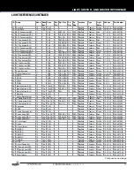
Страница 19: ...F ON ON OFF OFF OFF OFF OFF Germany ON ON ON OFF OFF OFF OFF OFF Greece ON ON ON ON OFF OFF OFF OFF Italy OFF OFF OFF ON OFF OFF OFF OFF Japan ON OFF ON OFF ON OFF OFF OFF Middle East ON ON ON OFF ON OFF OFF OFF Netherlands OFF OFF ON OFF OFF OFF OFF OFF New Zealand OFF OFF OFF OFF ON OFF OFF OFF Norway OFF ON OFF ON OFF OFF OFF OFF Portugal ON OFF OFF OFF OFF ON OFF OFF Russia ON OFF OFF ON ON OF...

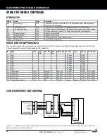
Страница 20: ...xD Node bus receive Red Node bus receive activity Status System status Red Constant double blink game software running Netstat Network status Red Communication bridge activity DIRECT SWITCH MAPPING CN25 The coin door diagnostic switches are connected directly to the CPU node via the Cabinet Node Note that both the CPU and Cabinet nodes are required for diagnostic switch operation ID Name Conn Inpu...

Страница 21: ...LK WHT 6 Spare Left 7 Tilt Input WHT 8 Door Open 9 Start 2 Switch GRY WHT 10 Start 1 Switch GRY 11 N C 12 N C 13 N C 14 N C CN7 100 12 Pin Header Cabinet Right 1 5V LED Power 2 Plunge 2 LED 3 Plunge 1 LED 4 Spare LED 2 5 Ground 6 Spare Right In 7 Plunge 2 Switch 8 Plunge 1 Switch 9 N C 10 N C 11 N C 12 N C CN9 100 6 Pin Header Dollar Bill Ac ceptor 1 Coin Enable DBA Inhibit 2 Coin Enable DBA Inhib...

Страница 22: ...Driver Return YEL ORG 4 48V Driver Power CN10 156 6 Pin Header Orange 1 8 LP 2 Light Return 2 LED V 3 Switch Ground BLK GRN 4 8 SW 6 Switch Return GRY VIO 5 8 DR 6 Driver Return ORG VIO 6 48V Driver Power GRY ORG CN11 156 4 Pin Header Green 1 Switch Ground BLK GRN 2 8 SW 3 Switch GRY RED 3 8 DR 3 Driver Return YEL GRN 4 48V Driver Power CN12 156 6 Pin Header Green 1 8 LP 3 Light Return 2 LED V 3 S...

Страница 23: ...EL 3 Switch Ground BLK BRN 4 9 SW 5 LGN BRN 5 9 DR 5 Driver Return ORG BRN 6 48V Driver Power GRY BLK CN9 156 4 Pin Header Orange 1 Switch Ground 2 9 SW 2 Switch 3 9 DR 2 Driver Return 4 48V Driver Power ID Type Pin Description Wire Color CN10 156 6 Pin Header Orange 1 9 LP 2 Light Return ORG RED 2 LED V YEL 3 Switch Ground BLK BRN 4 9 SW 6 Switch Return LGN RED 5 9 DR 6 Driver Return ORG RED 6 48...

Страница 24: ...LK BLU 4 10 SW 5 WHT RED 5 10 DR 5 Driver Return 6 48V Driver Power CN9 156 4 Pin Header Orange 1 Switch Ground BLK BLU 2 10 SW 2 Switch WHT VIO 3 10 DR 2 Driver Return YEL RED 4 48V Driver Power GRY BRN ID Type Pin Description Wire Color CN10 156 6 Pin Header Orange 1 10 LP 2 Light Return YEL RED 2 LED V 3 Switch Ground BLK BLU 4 10 SW 6 Switch Return WHT ORG 5 10 DR 6 Driver Return 6 48V Driver ...

Страница 25: ...ch Return 7 11 SW 21 Switch Return PNK GRN 8 11 SW 22 Switch Return 9 11 SW 23 Switch Return PNK VIO 10 Switch Ground BLK RED CN10 CN9 CN8 CN12 CN2 CN3 CN5 CN7 CN6 CN4 CN1 SW1 520 5322 00 32 SW 32 LED NODE GREEN GREEN ORANGE ORANGE BLACK BLACK NEUTRAL NEUTRAL 1 2 3 ON CN11 ID Type Pin Description Wire Color CN4 100 12 Pin Header Orange 1 8V 2 5V RED 3 5V RED 4 11 LP 8 Light Return RED YEL 5 11 LP ...

Страница 26: ... Return WHT BLU 8 11 SW 6 Switch Return WHT VIO 9 11 SW 7 Switch Return WHT GRY 10 Switch Ground BLK VIO CN8 100 12 Pin Header White 1 8V 2 5V RED 3 5V RED 4 11 LP 24 Light Return BRN BLK 5 11 LP 25 Light Return BRN RED 6 11 LP 26 Light Return BRN ORG 7 11 LP 27 Light Return BRN YEL 8 11 LP 28 Light Return BRN GRN 9 11 LP 29 Light Return BRN BLU 10 11 LP 30 Light Return BRN VIO 11 11 LP 31 Light R...

Страница 27: ...ANSMITTER 520 5344 00 ID Type Pin Description Wire Color CN1 100 3 Pin Header 1 Ground BLK 2 N C 3 5 VDC IN RED 4 10 TROUGH OPTO RECEIVER 520 5345 01 ID Type Pin Description Wire Color CN1 100 7 Pin Header 1 Ground BLK 2 MISO Output Data VIO BLK 3 MOSI Input Data 4 SCK Serial Clock VIO RED 5 RCK Register Clock VIO ORG 6 N C 7 5 VDC IN RED PINOUT 4 7 DUAL MOTOR DRIVER 520 5338 00 ID Type Pin Descri...

Страница 28: ...DC In GRY CN2 100 7 Pin Header 1 Ground BLK 2 MISO Output Data VIO BLK 3 MOSI Input Data VIO BRN 4 SCK Serial Clock VIO RED 5 RCK Register Clock VIO ORG 6 N C 7 5 VDC IN RED CN4 100 5 Pin Header 1 LED35 YEL RED 2 LED36 YEL BRN 3 LED37 ORG GRN 4 LED38 YEL ORG 5 5 VDC LED Supply RED CN6 100 7 Pin Header 1 LED52 RED WHT 2 LED53 GRN WHT 3 LED54 BLU WHT 4 LED55 ORG GRY 5 LED56 ORG WHT 6 LED57 ORG BLU 7...

Страница 29: ...ow MDL 200 5000 01 CAUTION TO MAINTAIN SAFETY GROUND WIRE FROM LINE FILTER IS TO BE MOUNTED FIRST ON GROUNDING STUD AND SECURED WITH NUT ALL OTHER GROUNDS MAY THEN BE ATTACHED TO GROUNDING STUD REPLACE ALL FUSES WITH CORRECT CURRENT RATINGS Part Number Description 034 6012 00 Line Cord 3m 5 15P USA 034 6012 01 Line Cord 3m CEE77P EUROPE 034 6012 02 Line Cord 3m BS1363P United Kingdom 034 6012 03 L...

Страница 30: ...chart and read largest size on inside of ring Dimensions are In ner Diameter ID unless otherwise noted as Outer Diamter OD 3 8 7 16 5 16 3 16 7 16 OD 3 8 OD 5 PARTS REFERENCE ID Qty Size ID Size OD Durometer Color Part Number 1 4 3 16 50 Black 545 5348 01 8 2 3 8 50 Black 545 5348 03 6 3 7 16 50 Black 545 5348 18 2 3 3 4 50 Black 545 5348 04 3 1 1 50 Black 545 5348 05 7 1 1 3 4 50 Black 545 5348 2...

Страница 31: ...an 1 8 550 7400 H1 DM Hot Stamped Bumper Cap Demon 1 9 550 7400 H1 SC Hot Stamped Bumper Cap StarChild 1 10 550 7400 H1 CM Hot Stamped Bumper Cap Cataman 1 11 500 9954 00 Left Plastic Ramp Assembly 1 12 535 1164 00 Left Wire Ramp 1 13 535 1182 00 Vuk Snubber 1 14 500 9952 00 Right Ramp Assembly 1 15 535 1165 00 Right Wire Ramp 1 16 511 7655 00 GE Spinner Assembly Left Hand 1 17 511 5240 01 SPI Spo...

Страница 32: ...83 ND Flip Asssembly LT with Coil 090 5083 03 ND 1 7 500 9907 00 00 1 2 S U Target Anti Sway ND 2 8 500 9904 00 00 1 SQ Target S U AntiLoft Light ND 12 9 515 6459 04 ND Pop Bumper Bottom Assy 26 1200 4 10 500 9934 01 Pop Bumper SW Assembly LT 4 11 500 6697 00 ND Kicker Lugs Up Assembly 1 12 500 9812 ND Power Scoop Assy with no diode 1 13 500 9920 01 RT Slingshot Assembly 26 1200 Right 2 14 500 651...

Страница 33: ...ption Qty 1 515 6957 10 CPU Node Board 10 w LCD Adapter 1 2 520 5343 00 Power Distribution Board 1 3 011 5001 00 Power Supply 48V 320W 1 4 515 9769 00 Utility Outlet USA 1 5 205 5001 00 Fuse Holder Screw in 1 6 535 0772 00 Cover AC 1 7 535 0879 01 Power supply bracket 1 8 535 0879 00 Power supply bracket 1 9 355 5168 00 Backbox Lock 5 8 in 1 10 180 5001 03 Power Switch 1 034 6012 00 Line Cord 3M 5...

Страница 34: ...S 1 820 66H1 03G DECAL CABINET LEFT KISS GERMANY 33 820 66H1 04 DECAL CABINET RIGHT KISS 1 820 66H1 04G DECAL CABINET RIGHT KISS GERMANY 34 820 66H1 05 DECAL CABINET FRONT KISS 1 820 66H1 05G DECAL CABINET FRONT KISS GERMANY 35 660 5001 00 PLAYFIELD GLASS 1 18 16 14 5 19 31 30 35 7 13 1 34 33 18 180 5160 01 SINGLE FLIPPER SWITCH 1 19 180 5160 00 FLIPPER SWITCH DOUBLE 1 20 355 5038 00 DRAW LATCH OV...

Страница 35: ... 2 13 535 6539 00 SWITCH BODY PROTECT PLATE 1 14 180 5157 01 SHOOTER SWITCH SHORT ARM 1 15 545 6268 00 FISCHE PAPER 1 16 535 0762 00 COIL BRACKET AUTOPLUNGER 1 17 515 6304 03 PLUNGER LINK ASSEMBLY 1 18 545 0762 00 FISCHE PAPER AUTO LAUNCHER 1 5 9 BALL TROUGH ASSEMBLY 500 9820 00 ID Part Number Description Qty 1 515 7811 00 MAIN BRKT BALL TROUGH 1 2 515 7812 00 COIL BRACKET BALL TROUGH 1 3 237 5975...

Страница 36: ... 1 14 515 6275 08 01 FLIPPER BAT AND SHAFT RED MINI 500 6543 15 ND Assy 1 500 6307 10 FLIPPER REBUILD KIT LEFT Refer to game rubber chart for flipper rubber color and part number 5 11 FLIPPER ASSEMBLY RIGHT 500 6543 82 ND Figure 5 11 1 Right flipper assembly 500 6543 12 ND bottom view 1 2 3 4 11 13 6 8 7 10 14 5 9 ID Part Number Description Qty 1 515 6617 00 FLIPPER BASE PLATE RIGHT KIT W BRACKET ...

Страница 37: ... 32 X 3 8 PPH SEMS 2 6 180 5231 00 SLING SHOT SWITCH 2 LUG STANDARD LUGS 1 7 535 5045 00 SWITCH PLATE 2 8 237 5976 04 SCREW 6 32 X 5 8 HWH SWAGE 2 9 515 5340 01 ARM TIP ASSY 1 10 270 5002 00 RETAINING RING 1 4 2 11 515 5338 00 PLUNGER LINK ASSEMBLY 1 12 266 5020 00 COMPRESSION SPRING CONICAL 1 ID Part Number Description Qty 1 830 7028 02 BUTYRATE SET 02 1 2 550 5031 02 MINI MARS W EARS RED SB 1 3 ...

Страница 38: ... 7 232 5300 00 SCREW 8 32 X 1 4 PPH SEMS 2 8 180 5209 00 SUB MINIATURE SWITCH SIM ROLLER 1 9 535 6539 00 SWITCH BODY PROTECT PLATE 1 10 237 5937 02 SCREW 2 56 X 1 2 HWH MS 2 11 545 5105 00 RUBBER BUMPER 1 97 605 5002 00 SHRINK TUBING 1 8 BLACK 083 FT 98 605 5006 00 SHRINK TUBING 1 8 083 FT 99 036 6246 00 CABLE GENERIC COIL W SWITCH 1 5 16 UP POST VUK ASSEMBLY 550 9965 00 4 5 6 7 3 8 2 1 4 5 6 7 3 ...

Страница 39: ...BUMPER SWITCH ASSY 2 LUG LEFT 1 9 240 5005 00 6 32 NYLON STOP NUT 1 10 090 5044 ND COIL 26 1200 1 11 237 5976 01 6 32 X 1 4 SHWH SWAGE ZN 2 12 240 5005 00 6 32 NYLON STOP NUT 9 13 535 7347 00 METAL YOKE STOP 1 14 234 5101 00 8 X 1 2 SLT 6 15 530 5348 00 PLUNGER POP BUMPER 1 16 266 5047 00 COMPRESSION SPRING POP BUMPER 1 17 545 5031 00 COIL SLEEVE 1 18 515 5939 00 COIL BRACKET POP BUMPER ASSY 1 19 ...

Страница 40: ... 14 1 2 880 6175 00 AMPLIFIER MODEL 1 3 820 8380 33 DECAL SET 33 1 4 820 8380 34 DECAL SET 34 1 5 237 5833 00 SCREW 4 X 5 8 PFH BLACK 4 5 19 AMPLIFIER ASSEMBLY 511 7674 00 2 4 3 1 5 ITEM NO PART NUMBER DESCRIPTION QTY 1 830 7029 14 BUTYRATE SET 14 1 2 880 6175 00 AMPLIFIER MODEL 1 3 820 8380 33 DECAL SET 33 1 4 820 8380 34 DECAL SET 34 1 5 237 5833 00 SCREW 4 X 5 8 PFH BLACK 4 5 20 LEFT RAMP ASSY ...

Страница 41: ...008 32 HEX SPACER 2 1 8 1 3 232 5201 00 SCREW 6 32 X 3 8 PPH MS SEMS 1 2 1 3 ITEM NO PART NUMBER DESCRIPTION QTY 1 830 7028 06 BUTYRATE SET 06 1 2 254 5008 32 HEX SPACER 2 1 8 1 3 232 5201 00 SCREW 6 32 X 3 8 PPH MS SEMS 1 ID Part Number Description Qty 1 830 7028 08 BUTYRATE SET 08 1 2 254 5008 04 HEX SPACER 3 4 1 3 232 5201 00 SCREW 6 32 X 3 8 PPH MS SEMS 1 5 24 PLASTIC ASSY 08 511 7641 08 3 2 1...

Страница 42: ... 1154 03 STAR BALL GUIDE 03 1 2 515 0215 00 LONG RANGE OPTO EMITTER ASSEMBLY 1 3 237 5880 02 SCREW 6 X 1 2 PPH T 25 2 4 545 9815 00 OPTO SENSOR PROTECTOR 1 5 28 BALL GUIDE ASSEMBLY 03 511 7642 03 3 1 4 2 ITEM NO PART NUMBER DESCRIPTION QTY 1 535 1154 03 STAR BALL GUIDE 03 1 2 515 0215 00 LONG RANGE OPTO EMITTER ASSEMBLY 1 3 237 5880 02 SCREW 6 X 1 2 PPH T 25 2 4 545 9815 00 OPTO SENSOR PROTECTOR 1...

Страница 43: ...ID Part Number Description Qty 1 535 0278 02 MOUNTING BRACKET STAR 1 2 515 7715 02 MOTOR BRACKET STAR 1 3 511 5190 00 SOLDER ASSY SPINNING DISK MOTOR 1 4 237 6014 00 M5 X 0 8 X 8 PH SELF LOCKING SCREW 4 5 242 5028 00 WASHER NYLON 265 X 688 X 063 1 6 515 7714 02 DISK HUB WELDMENT STAR 1 7 237 6092 00 SET SCREW 10 32 X 5 16 SOCKET CUP PT 1 8 545 9807 00 ADHESIVE PAD SPINNING DISK STAR 1 9 237 5995 0...

Страница 44: ...ent attract mode 70 W 0 6 A 120 VAC 70 W 0 3 A 240 VAC Line Power Current nominal 360 W 3 A 120 VAC 360 W 1 5 A 240 VAC Line Power Current peak 100 ms 540 W 4 5 A 120 VAC 540 W 2 25 A 240 VAC NOTE Games designed for 60hz operation e g North Amer ica games will not function correctly on 50hz power and vice versa WARNING Overloading electrical supply circuits is dangerous Do not overload circuits To...

Страница 45: ...ake great care when servicing any game Always read the service manual before replacing or servicing com ponents SUBSTITUTIONS OF PARTS OR EQUIPMENT MODIFICATIONS may void FCC Type acceptance Always disconnect the line voltage before servicing Some parts may still hold current when unplugged WARNING This equipment generates uses and can radiate radio frequency energy and if not installed and used i...

Страница 46: ...1 800 KICKERS PARTS SERVICE STERNPINBALL COM WWW STERNPINBALL COM FACEBOOK COM STERNPINBALL KISS PRO MODEL 500 55H1 01 MANUAL PART 780 50H1 01 07 07 15 EDITION 780 50H1 01 ...

Отзывы: