


30
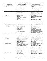
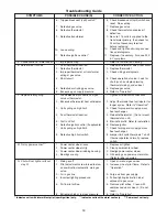
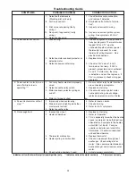
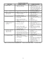
Troubleshooting Guide
SYMPTOMS
POSSIBLE CAUSE(S)
CORRECTIVE ACTION
6. Check blocked vent (spill) switch and
reset. See venting.
7. Replace gas valve.
8. Check thermostat and replace if
defective.
9. Be sure 115 volts is supplied to the
transformer primary, then check for
24 volts at secondary terminal
before replacing.
10. Check and tighten all wiring connec-
tions per diagrams.
11. Replace, if necessary. Also see W, X
& Y symptoms.
1. Refer to "Installation, Venting".
1. Relocate thermostat away from drafts.
2. Replace thermostat.
3. Check wiring per diagrams.
4. Check operation at valve. Look for
short (such as staples piercing
thermostat wiring), and correct.
5. Replace gas valve.
6. Refer to "Operation".
1. Tighten all electrical connections.
2. Adjust thermostat heat anticipator for
longer cycles. Refer to "Operation".
3. Check for proper air supply across
heat exchanger.
4. Relocate thermostat. (Do not mount
thermostat on unit).
5. Eliminate drafts. Refer to Installation.
6. Replace ignitor.
7. Check for proper air supply across
heat exchanger.
8. Jumper limit switch terminals 1 and 2.
If burner operates normally, replace
switch.
1. Replace or tighten.
2. Clean power venter wheel.
3. Realign power venter wheel.
4. Oil bearings on power venter motor.
(Refer to label on motor).
1. Open all manual gas valves.
2. Increase size of pilot flame. Refer to
"Operation".
3. Purge air from gas supply.
4. Follow lighting instruction label
adjacent to gas valve.
5. Remove pilot orifice. Clean with
compressed air or solvent. (Do not
ream).
6. Refer to "Operation".
6. Tripped block vent (spill) switch.**
7. Defective gas valve.
8. Defective thermostat
9. Defective transformer.
10. Loose wiring.
11. Defective ignition control.*
1. Improper venting.
1. Poor thermostat location.
2. Defective thermostat
3. Improper thermostat or transformer
wiring at gas valve.
4. Short circuit.
5. Defective or sticking gas valve.
6. Excessive gas supply pressure.
1. Loose electrical connections at gas
valve or thermostat.
2. Excessive thermostat heat anticipator.
3. Unit cycling on high limit.
4. Poor thermostat location.
5. Draft on Pilot.
6. Defective ignitor control (if applicable).
7. Unit cycling on high limit.
8. Defective high limit switch.
1. Power venter wheel loose.
2. Power venter wheel dirty.
3. Power venter wheel rubbing housing.
4. Bearings are dry.
1. Main gas off.
2. Pilot adjustment screw turned too low
on combination/automatic main gas
valve.
3. Air in gas line.
4. Incorrect lighting procedure.
5. Dirt in pilot orifice.
6. Extremely high or low gas pressure.
J. Condensation of water vapor.
K. Burner won't turn off.
L. Rapid burner cycling.
M. Noisy power venter.***
N. Pilot will not light or will not
stay lit.
* Indicates units with intermittent pilot (spark ignition) only. ** Indicates units with natural vent only. *** Power vent unit only.
Содержание NATURAL INDOOR GAS-FIRED DUCT FURNACE
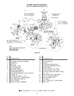
Страница 14: ...14 Figure 12A Figure 12B...
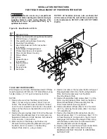
Страница 15: ...15 Figure 13A Figure 13B...
Страница 34: ...34 NOTES...
Страница 36: ......


