


11
VENTING
ANSI now organizes vented
appliances into four categories.
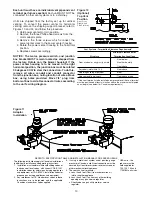
VENTING FOR NATURAL VENTED (CATEGORY
I
) DUCT FURNACES
(Figures 1 and 2)
ALL DUCT FURNACES MUST BE VENTED!
All venting installations shall be in accordance with “Part
7 , Venting of Equipment of the National Fuel Gas Code,
ANSI Z223.1, or applicable provisions of local building
codes.” See below for Canadian Installations. *
CARBON MONOXIDE! Your
venting system must not be blocked by any snow,
snow drifts, or any foreign matter. Inspect your
venting system to ensure adequate ventilation
exists at all times! Failure to heed these warnings
could result in Carbon Monoxide Poisoning
(symptoms include grogginess, lethargy,
inappropriate tiredness, or flu-like symptoms).
This duct furnace is equipped with a
blocked vent (spill) shutoff switch.
Before start up, push reset button on blocked vent
(spill) shutoff switch.
If the venting system becomes blocked or there is
continuous spillage, the vent shutoff switch will shut
off the duct furnace. Before resetting the switch,
check to see if the vent system is blocked; remove
any blockage.
To reset the switch (which is located in the upper
corner of the draft diverter), push the reset button
after the duct furnace has cooled down.
NOTICE: The switch will not reset hot.
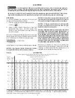
Observe the following precautions when venting the unit:
1. Use flue pipe of the same size as the flue
connections on the gas duct furnace (See Table #1).
All heaters should be vented with a UL Listed Type B
vent; a factory built chimney or a lined brick and
mortar chimney that has been constructed in
accordance with the National Building Code.
2. Where two or more gas duct furnaces vent into a
common flue, the cross sectional area of the
common flue must be equal to the largest vent
connection, plus 50% of the area of each additional
vent connection.
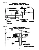
3. Provide as long a vertical run of flue at the gas duct
furnace as possible. A minimum of five feet (1.52m)
of vertical flue is required. The top of the vent pipe
should extend at least two feet (.61 m) above the
highest point on the roof. Install a weather cap over
the vent opening.
4. Slope horizontal runs upward from the gas duct
furnace at least 1/4-inch per foot (21mm/m).
Horizontal runs should not exceed 75% of the vertical
height of the vent pipe, or chimney, above the flue
pipe connection, up to a maximum length of 10 feet
(3m). Horizontal portions of the venting system shall
be supported at maximum intervals of four feet
(1.22m) to prevent sagging. See Figure 9.
Category
I
Includes non-condensing
appliances with negative vent
pressure, like the traditional
atmospheric unit heater.
Category
II
Groups condensing appliances
with negative vent pressure.
Category
III
Appliances are non-condensing
and operate with a positive vent
pressure.
Category
IV
Covers condensing appliances
with positive vent pressure.
NOTICE: Category
II
and
IV
do
not apply to equipment specified
within this manual.
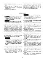
Venting Categories
Non
Condensing
Condensing
Negative
Vent
I
II
Pressure
Positive
Vent
III
IV
Pressure
Figure 9
*
The following instructions apply to Canadian
installations in addition to installation and operating
instructions:
1. Installation must conform with local building codes,
or in absence of local codes, with current CGA
B149.1, Installation Codes for Natural Gas Burning
Appliances and Equipment, or CGA B149.2,
Installation Codes for Propane Gas Burning
Appliances and Equipment.
2. Any reference to U.S. standards or codes in these
instructions are to be ignored and the applicable
Canadian standards or codes applied.
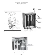
Содержание NATURAL INDOOR GAS-FIRED DUCT FURNACE
Страница 14: ...14 Figure 12A Figure 12B...
Страница 15: ...15 Figure 13A Figure 13B...
Страница 34: ...34 NOTES...
Страница 36: ......


