


55
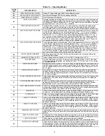
Table 29 — Alarm and Alert Codes (cont)
ALARM/
ALERT
CODE
ALARM
OR
ALERT
DESCRIPTION
WHY WAS THIS
ALARM
GENERATED?
ACTION TAKEN
BY CONTROL
RESET
METHOD
PROBABLE
CAUSE
A140
Alert
Reverse Rotation
Detected
Incoming chiller power
leads not phased correctly
Chiller not allowed to
start.
Manual
Reverse any two
incoming power
leads to correct.
Check for correct fan
rotation first.
A150
Alarm Emergency Stop
S
CN emergency stop
command received
Chiller shutdown
without going through
pumpdown.
Automatic once
S
CN
command for
EMSTOP returns to
normal
S
CN Network
command.
A151
Alarm
Illegal Configuration
One or more illegal
configurations exists.
Chiller is not allowed to
start.
Manual once
configuration errors
are corrected
Configuration error.
Check unit settings.
A152
Alarm
Unit Down Due to
Failure
Both circuits are down due
to alarms/alerts.
Chiller is unable
to run.
Automatic once
alarms/alerts are
cleared that prevent
the chiller from
starting.
Alarm notifies user
that chiller is 100%
down.
T153
Alert
Real Time Clock
Hardware Failure
Internal clock on MBB fails
Occupancy schedule
will not be used. Chiller
defaults to Local On
mode.
Automatic when
correct clock control
restarts.
Time/Date/Month/
Day/Year not
properly set.
A154
Alarm
Serial EEPROM
Hardware Failure
Hardware failure with MBB
Chiller is unable
to run.
Manual
Main Base Board
failure.
T155
Alert
Serial EEPROM
Storage Failure
Configuration/storage
failure with MBB
No Action
Manual
Potential failure of
MBB. Download
current operating
software. Replace
MBB if error occurs
again.
A156
Alarm
Critical Serial EEPROM
Storage Failure
Configuration/storage
failure with MBB
Chiller is not allowed
to run.
Manual
Main Base Board
failure.
A157
Alarm
A/D Hardware Failure
Hardware failure with
peripheral device
Chiller is not allowed
to run.
Manual
Main Base Board
failure.
A189
Alarm
Cooler pump auxiliary
contact inputs miswired
Pump 1 (2) aux contacts
closed when pump 2 (1)
energized.
Both pump outputs
are turned off.
Manual
Wiring error, faulty
pump contactor
auxiliary contacts.
T173
Alert
Loss of Communication
with EMM
MBB loses communication
with EMM
4 to 20 mA
temperature reset
disabled. Demand
Limit set to 100%. 4 to
20 mA set point
disabled.
Automatic
Wiring error, faulty
wiring or failed
Energy Manage-
ment Module (EMM).
T174
Alert
4 to 20 mA Cooling Set
Point Input Failure
If configured with EMM and
input less than 2 mA or
greater than 22 mA
Set point function
disabled. Chiller
controls to CSP1.
Automatic
Faulty signal
generator, wiring
error, or faulty EMM.
T176
Alert
4 to 20 mA
Temperature Reset
Input Failure
If configured with EMM
and input less than 2 mA or
greater than 22 mA
Reset function
disabled. Chiller
returns to normal set
point control.
Automatic
Faulty signal
generator, wiring
error, or faulty EMM.
T177
Alert
4 to 20 mA Demand
Limit Input Failure
If configured with EMM and
input less than 2 mA or
greater than 22 mA
Demand limit function
disabled. Chiller
returns to 100%
demand limit
control.
Automatic
Faulty signal
generator, wiring
error, or faulty EMM.
T189
Alarm
Cooler pump 2 and
Aux Contact Input
miswired
Alarm is generated when
the pump’s aux contacts
close when a pump is
called for
Chiller not allowed to
start
Manual
Wiring error
T190
Alert
Cooler pump 1 Aux
Contacts Failed to Close
at Start-Up
Pump 1 Auxiliary Contacts
did not close within
26 seconds after pump
was started
Pump 1 turned off.
Pump 2 will be started
if available.
Manual
Wiring error, faulty
contacts on pump
contactor
T191
Alert
Cooler pump 2 Aux
Contacts Failed to Close
at Start-Up
Pump 2 Auxiliary Contacts
did not close within
26 seconds after pump
was started
Pump 2 turned off.
Pump 1 will be started
if available.
Manual
Wiring error, faulty
contacts on pump
contactor
T192
Alert
Cooler pump 1 Failed
to Provide Flow at
Start-Up
Pump 1 did not provide
flow to close flow switch
within 60 seconds
Pump 1 turned off.
Pump 2 will be started
if available.
Manual
Wiring error, pump
circuit breaker
tripped, contactor
failure
T193
Alert
Cooler pump 2 Failed
to Provide Flow at
Start-Up
Pump 2 did not provide
flow to close flow switch
within 60 seconds
Pump 1 turned off.
Pump 2 will be started
if available.
Manual
Wiring error, pump
circuit breaker
tripped, contactor
failure
T194
Alert
Cooler pump 1 Aux
Contacts Opened
During Normal
Operation
Pump 1 Auxiliary Contacts
open for 26 seconds after
initially made. All
compressors shut down.
Pump 1 turned off.
Pump 2 will be started
if available. Chiller
allowed to run if
Pump 2 successfully
starts.
Manual
Wiring error, faulty
contacts on pump
contactor
T195
Alert
Cooler pump 2 Aux
Contacts Opened
During Normal
Operation
Pump 2 Auxiliary Contacts
open for 26 seconds after
initially made. All
compressors shut down.
Pump 2 turned off.
Pump 1 will be started
if available. Chiller
allowed to run if
Pump 1 successfully
starts.
Manual
Wiring error, faulty
contacts on pump
contactor
Содержание AquaSnap 30RA010
Страница 6: ...6 Fig 1 Typical Control Box for 30RA010 030 022 030 Shown ...
Страница 7: ...7 Fig 2 Typical Control Box for 30RA032 055 042 055 Shown ...
Страница 8: ...8 Fig 3 Wiring Schematic 30RA010 018 30RA010 018 AQUA SNAP ...
Страница 10: ...10 Fig 4 Wiring Schematic 30RA022 030 30RA022 030 AQUA SNAP ...
Страница 11: ...11 Fig 4 Wiring Schematic 30RA022 030 cont AQUA SNAP LOW VOLTAGE CONTROL SCHEMATIC 022 030 ...
Страница 12: ...12 Fig 5 Wiring Schematic 30RA032 040 30RA032 040 AQUA SNAP ...
Страница 13: ...13 Fig 5 Wiring Schematic 30RA032 040 cont AQUA SNAP LOW VOLTAGE CONTROL SCHEMATIC 032 040 ...
Страница 14: ...14 Fig 6 Wiring Schematic 30RA042 055 30RA042 055 AQUA SNAP ...
Страница 15: ...15 Fig 6 Wiring Schematic 30RA042 055 cont AQUA SNAP LOW VOLTAGE CONTROL SCHEMATIC 042 055 ...