


46
Table 27 — Configuring Demand Limit
*Seven items skipped in this example.
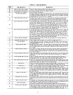
TROUBLESHOOTING
Complete Unit Stoppage and Restart —
Possi-
ble causes for unit stoppage and reset methods are shown be-
low. (See Table 28 also.) Refer to Fig. 22-26 for Component
Arrangement and Control Wiring Diagrams.
GENERAL POWER FAILURE — After power is restored,
restart is automatic through normal MBB start-up.
UNIT ENABLE-OFF-REMOTE CONTACT SWITCH IS
OFF — When the switch is OFF, the unit will stop immediate-
ly. Place the switch in the ENABLE position for local switch
control or in the REMOTE CONTACT position for control
through remote contact closure.
CHILLED FLUID PROOF-OF-FLOW SWITCH OPEN —
After the problem causing the loss of flow has been corrected,
reset is manual by resetting the alarm with the Scrolling Mar-
quee as shown in Table 24.
OPEN HIGH-PRESSURE SWITCH(ES) — Determine and
correct the cause of the failure. The switch automatically resets,
but the unit must be reset manually by resetting the alarm with
the Scrolling Marquee as shown in Table 24.
OPEN COMPRESSOR INTERNAL THERMAL PRO-
TECTION — This switch provides compressor over tempera-
ture protection. Determine and correct the cause of the prob-
lem. The switch resets automatically, but the unit must be reset
manually resetting the alarm with the Scrolling Marquee as
shown in Table 24.
OPEN 24-V CONTROL CIRCUIT BREAKER(S) — De-
termine the cause of the failure and correct. Reset circuit break-
er(s). Restart is automatic after MBB start-up cycle is com-
plete.
COOLING LOAD SATISFIED — Unit shuts down when
cooling load has been satisfied. Unit restarts when required to
satisfy leaving fluid temperature set point.
THERMISTOR FAILURE — If a thermistor fails in either an
open or shorted condition, the unit will be shut down. Replace
T1, T2, or T9 as required. Unit restarts automatically, but must
be reset manually by resetting the alarm with the Scrolling
Marquee as shown in Table 24.
LOW SATURATED SUCTION — Several conditions can
lead to low saturated suction alarms and the chiller controls
have several override modes built in which will attempt to keep
the chiller from shutting down. Low fluid flow, low refrigerant
charge and plugged filter driers are the main causes for this
condition. To avoid permanent damage and potential freezing
of the system, do NOT repeatedly reset these alert and/or alarm
conditions without identifying and correcting the cause(s).
MODE
KEYPAD
ENTRY
SUB-MODE
KEYPAD
ENTRY
ITEM
DISPLAY
ITEM EXPANSION
COMMENT
CONFIGURATION
DISP
TEST
ON/OFF
Test Display LEDs
UNIT
TYPE
X
Unit Type
OPT1
FLUD
X
Cooler Fluid
OPT2
CTRL
X
Control Method
RSET
CRST
X
Cooling Reset Type
DMDC*
X
Demand Limit Select
Default: 0
0 = None
1 = Switch
2 = 4 to 20 mA Input
3 =
S
CN Loadshed
DM20
XXX %
Demand Limit at 20 mA
Default: 100%
Range: 0 to 100
SHNM
XXX
Loadshed Group
Number
Default: 0
Range: 0 to 99
SHDL
XXX%
Loadshed Demand
Delta
Default: 0%
Range: 0 to 60%
SHTM
XXX MIN
Maximum Loadshed
Time
Default: 60 min.
Range: 0 to 120 min.
DLS1
XXX %
Demand Limit
Switch 1
Default: 80%
Range: 0 to 100%
DLS2
XXX %
Demand Limit
Switch 2
Default: 50%
Range: 0 to 100%
ENTER
ENTER
ENTER
ENTER
ENTER
ENTER
If unit stoppage occurs more than once as a result of any of
the safety devices listed, determine and correct cause
before attempting another restart.
Содержание AquaSnap 30RA010
Страница 6: ...6 Fig 1 Typical Control Box for 30RA010 030 022 030 Shown ...
Страница 7: ...7 Fig 2 Typical Control Box for 30RA032 055 042 055 Shown ...
Страница 8: ...8 Fig 3 Wiring Schematic 30RA010 018 30RA010 018 AQUA SNAP ...
Страница 10: ...10 Fig 4 Wiring Schematic 30RA022 030 30RA022 030 AQUA SNAP ...
Страница 11: ...11 Fig 4 Wiring Schematic 30RA022 030 cont AQUA SNAP LOW VOLTAGE CONTROL SCHEMATIC 022 030 ...
Страница 12: ...12 Fig 5 Wiring Schematic 30RA032 040 30RA032 040 AQUA SNAP ...
Страница 13: ...13 Fig 5 Wiring Schematic 30RA032 040 cont AQUA SNAP LOW VOLTAGE CONTROL SCHEMATIC 032 040 ...
Страница 14: ...14 Fig 6 Wiring Schematic 30RA042 055 30RA042 055 AQUA SNAP ...
Страница 15: ...15 Fig 6 Wiring Schematic 30RA042 055 cont AQUA SNAP LOW VOLTAGE CONTROL SCHEMATIC 042 055 ...


