EHU WIRING INSTRUCTIONS
Tech Support:
consumer.steppir.com/support | 425.453.1910 | [email protected]
23
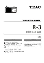
6 Pin Header Wiring Sequence
(EHU’s
with Relays)
4 Pin Header Wiring Sequence
(EHU’s
without Relays)
BLACK
WHITE
BLUE
BROWN
TERMINAL PLUG
FIG. 3.14
TERMINAL HEADER
GREEN
RED
•
Once you have cut the control cable for each element repeat the following steps for each cable:
1. Trim approximately 1.5 inches of the outer jacket of one end of the control cable.
2. Remove the shield material, the support thread and cut the ground wire off as shown in
figure 3.11
.
3. Attach electrical tape at the end of the trimmed control cable jacket so that there is no chance for a short.
4.
Remove 0.25 inches of the insulation from each of the individual 22 AWG wires, leaving bare copper.
Figure
3.1
shows the control cable should look like when you are finished with the trimming (6 conductor is shown).
5. Dip each of the copper wires into connector protector.
Figure 3.12
shows what the connector protector will
look like.
6. Remove the green phoenix terminal plug from the EHU header and use a flathead screwdriver to open the
terminals.
7. Insert the wires into the appropriate terminal following the wiring sequence shown in
figure 3.14
. Be careful
to ensure that there are no bare wires protruding out from the terminal clamps.
Also be sure that when you
tighten the terminals you are clamping on the bare wire and not the insulation! This can happen if
you
don’t strip enough insulation off the wires or if you insert them too far into the terminal.
FIG. 3.11
FIG. 3.12
FIG. 3.13
BLACK
RED
GREEN
WHITE