-
--
2
2
/
5
e
g
a
P
-
--
CUnet Family MKY44-IO32A
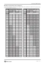
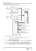
The DIO mode of the MKY44-IO32A occupies the MB (Memory Block) of the SA value that is set by SA0 to SA5 of the ST44SW.
The status of the general-purpose I/O pins (Io00 to Io07, Io10 to Io17, Io20 to Io27, Io30 to Io 37) is stored in bits 0 to 31 of the MB
occupied by the DIO mode of the MKY44-IO32A. Among the statuses of the general-purpose I/O pins stored in bits 0 to 31, the
, the latest value loaded in each
Bit
15
14
13
12
11
10
9
8
7
6
5
4
3
2
1
0
Content Io17
Io16
Io15
Io14
Io13
Io12
Io11
Io10
Io7
Io6
Io5
Io4
Io3
Io2
Io1
Io0
Bit
31
30
29
28
27
26
25
24
23
22
21
20
19
18
17
16
Content Io37
Io36
Io35
Io34
Io33
Io32
Io31
Io30
Io27
Io26
Io25
Io24
Io23
Io22
Io21
Io20
Bit
47
46
45
44
43
42
41
40
39
38
37
36
35
34
33
32
Content DFon DOSA5 DOSA4 DOSA3 DOSA2 DOSA1 DOSA0 DOHL FD3
FD2
FD1
FD0
“0”
IOSWAP IOS1
IOS0
Bit
63
62
61
60
59
58
57
56
55
54
53
52
51
50
49
48
Content
“0”
FI9
FI13
FI12
FI11
FI10
FI8
FI7
FI6
FI5
FI4
FI3
FI2
FI1
FI0
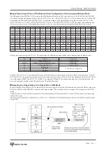
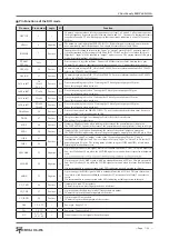
Setting values are stored in bits 32 to 63. These bits show the following settings, loaded when returning from a hardware reset.
Bit
Content
Description
47
DFon (DIP-SW1: 8)
“1” when it is ON
46 to 41
DOSA5 to DOSA0 (DIP-SW1: 6 to 1)
DOSA value
40
DOHL (DIP-SW1: 7)
“1” when it is ON
34
IOSWAP pin
“1” when the pin is High-level
33
IOS1 pin
32
IOS0 pin
7KLVYDOXHLVKH[DGHFLPDOE\WHVLQXQLWVRIȝV
The valid range is 0x0001 to 0x2710 (1 to 10,000). The settings of FD and FI can be changed using the CUnet mail function. For
how to change them, see the section “Support for the CUnet Mail Function”.
FI13, bits 48 to 61,
Selecting the Output Data to the Output Pins in DIO Mode
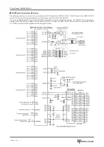
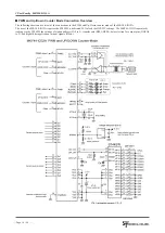
In the DIO mode of the MKY44-IO32A, the data of the lower or upper 32 bits in the MB (Memory Block) for the DOSA value set by
DOSA0 to DOSA5 of the ST44SW is selected as the data to output. The selection of lower or upper 32 bits is based on the DOHL
setting.
get pins
with positive logic.
of pin STB1.


