


rev 11/97
7 - 6
09-282C
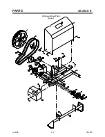
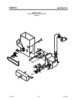
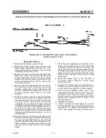
Assembly Instructions for: MODEL CS313 CHIPPER / SHREDDER BLOWER
Refer to Section 6 Parts
Drawing for Identification of
Parts.
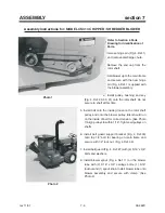
1. Remove hinge pin (Fig. 4, Ref. 1)
and remove discharge chute.
2. Remove the end cap from the
rotor shaft.
3. Hold blower up to the main frame
and secure with the new hinge
pin (Fig, 4, Ref. 1) supplied with
the blower assembly.
4. Install pulley, bushing and key
(Fig. 4, Ref. 29, 30, 31) onto the rotor shaft. Do not
secure to shaft at this time.
5. Install belt onto the inside groove on the rotor shaft
pulley, and onto the blower pulley. Idler should run
on the inside of belt for correct tension. (See Photo
1) Align pulleys to within 1/16". Tighten all pulleys on
shafts.
6. Install belt guard support bracket (Fig. 4, Ref.33)
onto top 1/2" bolt for bearing on main frame and
secure with 1/2" lock nut. (Fig. 4, Ref. 32)
7. Install belt guard (Fig. 4, Ref. 27) with (4) 5/16" x 3/4"
bolts and washers.
8. Install blower spout (Fig. 4, Ref. 11) on the blower
tube with (2) 5/16" x 3/4" carriage bolts, (1) 5/16"
locknut and (1) spout knob. Install blower tube onto
blower assembly and secure with clamp. (See
Photo 2)
Photo 1
Photo 2
ASSEMBLY
section 7
Содержание CS312
Страница 16: ...rev 8 98 6 2 09 282C PARTS section 6 Hitch and Drive Parts Figure 1 ...
Страница 18: ...rev 5 00 6 4 09 282C PARTS section 6 Frame Parts Figure 2 ...
Страница 20: ...rev 8 98 6 6 09 282C PARTS section 6 Emergency Stop Switch Parts Figure 3 ...
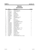
Страница 22: ...rev 5 00 6 8 09 282C PARTS section 6 MODEL CS313 Chipper Shredder Blower Parts Figure 4 ...
Страница 30: ......