


rev 8/97
7 - 4
09-282C
ASSEMBLY
section 7
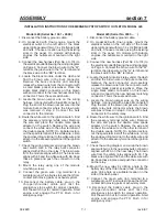
INSTALLATION INSTRUCTIONS FOR EMERGENCY STOP SWITCH OUTLET ON MODEL 525
Model 525 Tractors:
1. Disconnect the battery ground cable.
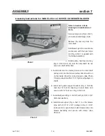
2. Mount the electrical outlet on the left side of the
black upper grille panel with two 1/4 x 3/4
flange bolts and nuts. Choose a location using
the existing slots in the panel.
3. Remove the dash access panel. Starting at the
dash area, route the new harness (the end
without terminals) along the existing wiring
harness through the center pivot area of the
tractor. Continue routing until the wires reach
the electrical outlet.
4. Connect the new harness (Part No. 30--187) to
the electrical outlet following the wiring
diagram on this page. Connect the blue wire to
the “W” terminal, the green wire to the “G”
terminal and the black wire to the “BK”
terminal.
5. Locate the clutch relay and circiut breakersin
the dash area. Near the breakers find the
harness with two blue wires that comes from
the seat switch. Disconnect the bullet
connector on the blue seat switch wire and
connect the female bullet connector of the 5
inch brown wire to the male bullet connector on
the blue seat switch wire. Connect the male
bullet of the new green wire to the female bullet
connector of the blue wire that goes to the front
lift limit switch.
6. Route the blue wire from the new harness to the
PTO switch. Find the PTO switch terminal with
the blue wire attached. Remove the wire and
place the double male spade adapter on the
switch. Replace the wire and connect the new
blue wire to the other terminal of the double
spade.
7. Check the wiring diagram and snap the 5 inch
brown seat switch wire in the relay bulk
connector aligned with 87A on the relay. The
green wire from the new harness aligns with 30.
The black wire aligns with 85 and the 10 inch
black wire with ring terminal with 86. Snap
these in place and push the connector on the
safety relay.
8. Mount the safety relay on the left side of
mounting panel using the clutch relay
mounting screw.
9. Connect the black wire ring terminal to a
suitable ground. Tie all wires to keep them from
contact with moving parts or exhaust system.
10. Reconnect the battery cable, plug in the
c h i p p e r / s h r e d d e r c a b l e a n d t e s t t h e
emergency stop switch for proper operation.
Pull the switch out for normal operation. Start
engine and engage the PTO. Push in for
emergency stop.
11. Replace all shields.
12. Proper operation will disengage the electric
PTO clutch when the emergency stop switch is
pushed “IN”. To restart, pull emergency knob
“OUT” and engage PTO in the normal manner.
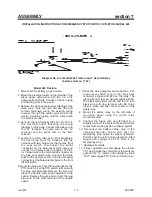
Diagram No. 2 for Model 525 Tractors w/o 2 Second Delay
(before serial no. 1197)
Содержание CS312
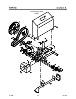
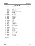
Страница 16: ...rev 8 98 6 2 09 282C PARTS section 6 Hitch and Drive Parts Figure 1 ...
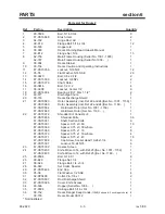
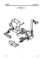
Страница 18: ...rev 5 00 6 4 09 282C PARTS section 6 Frame Parts Figure 2 ...
Страница 20: ...rev 8 98 6 6 09 282C PARTS section 6 Emergency Stop Switch Parts Figure 3 ...
Страница 22: ...rev 5 00 6 8 09 282C PARTS section 6 MODEL CS313 Chipper Shredder Blower Parts Figure 4 ...
Страница 30: ......