ST1006/ST1011 8" Jointer (Mfd. Since 3/16)
-39-
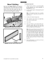
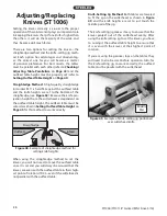
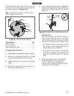
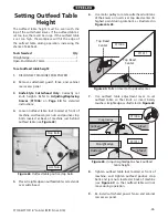
Figure 50. Cutterhead profile diagram.
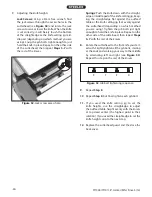
To adjust/replace the knives:
1. DISCONNECT JOINTER FROM POWER SOURCE!
2. Remove the cutterhead guard from the table
and move the fence back as far as it will go.
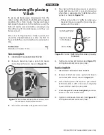
3. Open the back cover to expose the cutterhead
pulley.
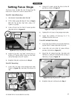
4. Rotate the cutterhead pulley to get access to
one of the cutterhead knives.
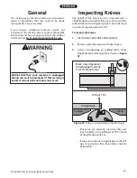
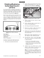
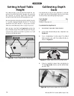
Figure 51. Gib bolt loosening/tightening direction.
Tightens
Knife
Loosens
Knife
5. Loosen the cutterhead gib bolts (see Figure 51),
starting in the middle, and alternating back and
forth until all of the gib bolts are loose, but not
falling out.
6. Remove and clean the gibs and clean inside
the cutterhead slot to remove all pitch or
sawdust. Coat the knives and gibs with a
metal protectant, then fit the gibs back in the
cutterhead with the new knives.
The Model ST1006 comes with both jack screws and
springs inside the cutterhead to provide two options
for adjusting the knives (see Figure 50).
Note:
Only one of these options is needed to set the
knives—
Step 5
gives the details.
Tools Needed
Qty
Knife-Setting Jig ................................................................... 1
Hex Wrench 3mm ................................................................. 1
Open-End Wrench 10mm.................................................. 1
First Time Only
If this is the first time you are setting the knives,
remove the gib and knife from the cutterhead.
Decide which adjustment option you are going
to use between the jack screws and the springs.
—If you decide to use the jack screws, remove
the springs from the cutterhead (they are
located directly below the knives).
—If you decide to use the springs, just thread the
jack screws completely into the cutterhead so
they will not get lost. Replace the gib and
knife.

