Page 4 of 7
939568007 Rev B
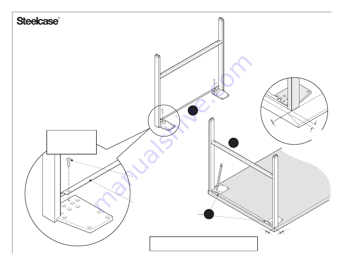
5.
Turn leg frame over and attach the trim strip to the
legs, making sure it is tight to each leg. Use #8 x .375
flat head screws to attach the trim.
6.
Position the leg assembly so that it is centered on
the top side to side and inset from the front 3/16".
7.
Mark mounting plate holes onto the top and drill pilot
holes. Use a .125" diameter bit, making the holes
approximately 3/4" deep.
5
6
REPEAT FOR OTHER SIDE
MAKE ALL HOLES
WITH COUNTERSINKS
REF
3/16"
TRIM STRIP
#8 X .375 FLAT
HEAD SCREW
TIP: For back-to-back gate leg application, make this
(REF) dimension zero or flush to back of worksurface.
Tip: Make sure that the
torque control drill is set
properly to prevent
stripping of screws.
FOR BLADE EDGE WORKSURFACES ONLY:
The outer surface of the gate leg must be
inset from the edge of the worksurface by 3/4"
REF
3/4"
(18.4 mm)
7


