


P-1
P-2
P-3
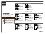
Line 1 (Black)
Line 3 (Blue)
Line 2 (Red)
L3 Neutral (White/Gray)
L1 Neutral (White)
L2 Neutral (Gray)
Isolated Ground (Gn/Yl)
Systems Ground (Green)
NEUTRAL
GROUND
P-1
P-2
P-3
Line 1 (Black)
3 SepN Powered by Separate Panels
Line 2 (Red)
Systems Ground (Green)
GROUND
3 SepN Powered by Single Panel
P-1 P-2
Line 1 (Black)
Line 3 (Blue)
Line 2 (Red)
L3 Neutral (White/Gray)
L1 Neutral (White)
L2 Neutral (Gray)
Isolated Ground (Gn/Yl)
Systems Ground (Green)
NEUTRAL
GROUND
3 SepN Powered by Split-Phase Panel
P-1
P-2
P-3
Line 3 (Blue)
L3 Neutral (White/Gray)
Isolated Ground (Green/Yellow)
NEUTRAL
GROUND
L2 Neutral (Gray)
L1 Neutral (White)
NEUTRAL
P-1
P-2
P-3
Line 1 (Black)
Line 4 (Pink)
Line 3 (Blue)
Line 2 (Red)
L3/L4 Neutral (Gray)
L1/L2 Neutral (White)
Isolated Ground (Gn/Yl)
System Ground (Green)
NEUTRAL
GROUND
P-1
P-2
P-3
Line 1 (Black)
2+2 Powered by Separate Panels
Line 2 (Red)
L1/L2 Neutral (White)
System Ground (Green)
NEUTRAL
GROUND
GROUND
P-1
P-2
P-3
Line 3 (Blue)
Line 4 (Pink)
L3/L4 Neutral (Gray)
Isolated Ground (Gn/Yl)
NEUTRAL
2+2 Powered by 3-Phase Single Panel
NOTE: L-4 should alternate between
P-1 and P-2 to balance circuit loading.
P-1 P-2
Line 1 (Black)
Line 4 (Pink)
Line 3 (Blue)
Line 2 (Red)
L3/L4 Neutral (Gray)
L1/L2 Neutral (White)
Isolated Ground (Gn/Yl)
System Ground (Green)
NEUTRAL
GROUND
2+2 Powered by Split-Phase Panel
NOTE: Line 3 or 4 should alternate between
phases to balance circuit loading.
NOTE: L-4 should alternate between P-1,
P-2, and P-3 to balance circuit loading.
3+1 Powered by Separate Panels
NOTE: L-4 may be connected
to P-1, P-2, or P-3.
3+1 Powered by Single Panel
P-1
P-2
P-3
Line 1 (Black)
Line 2 (Red)
Line 3 (Blue)
L1/L2/L3 Neutral (White)
Systems Ground (Green)
NEUTRAL
GROUND
GROUND
P-1
P-2
P-3
Line 4 (Pink)
L4 Neutral (Gray)
Isolated Ground (Gn/Yl)
NEUTRAL
P-1
P-2
P-3
LINE 1 (Black)
LINE 4 (Pink)
LINE 3 (Blue)
LINE 2 (Red)
L4 Neutral (Gray)
L1/L2/L3 Neutral (White)
Isolated Ground (Gn/Yl)
Systems Ground (Green)
NEUTRAL
GROUND
ELECTRICAL DATA:
120 V 60 HZ 20 Amp USA & CANADA
Wiring schematics must be followed
to prevent overloading of the neutrals.
WIRING SCHEMATICS:
Page 10 of 10
939504633 Rev Y
WARNING
Risk of Fire or Electric Shock
This office furnishing system may be
connected to more than one source
of supply. All sources must be
disconnected prior to any servicing.
No single circuit may be powered by
more than one source.


