Failure analysis
PF166
Pfad \ Datei:
I:\Projekte\SOLAR\PV-Entw\FREEZER\_E5970_KS-solar-LHG\14_Service\Failure analysis.doc
Seite 3 von 5
Speicherdatum:
Bearbeiter: Gutzeit
4.
Check inverter box
(beside the compressor)
[235]
The signal to start the compressor
[230]
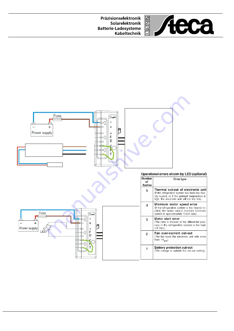
will be activated by a short circuit between "C" and
"T". There is no risk of high voltage, sparks or high current. You can use even a not isolated
cable. If the thermostat-display-electronic
[40]
failed the compressor
[230]
could be started
manually by a short circuit between "C" and "T" of the inverter box
[235]
Before short circuiting the terminal "C" and "T" to start the compressor
[230]
manually please
disconnect all connectors coming from the display-electronic
[40]
. First brown "+" cable
above "F" than the black "T" and blue "C" cable. If the inverter box
[235]
is connected to the
battery and if the battery voltage is higher than the cut-off voltage the compressor
[230]
must start suddenly after disconnecting "C" and "T".
If the compressor
[230]
do not start the inverter or the compressor
[230]
could be damaged
Display
Electronik
Sensor
Compressor
5.
Compressor
[230]
If you connect an LED to the "+" terminal above "F"
and to the "D" terminal (see picture 2) you could
have a feedback if the inverter box
[235]
is
operating and some other events are responsible
why the compressor
[230]
don't starts. See table.
Compressor
6.
Electronic thermostat with user interface (display and key board)
[40]
If the display
[40]
monitors no number or if the Minus-LED is not blinking please disconnect
the blue cable "C" on the inverter box
[235]
as well as the other blue cable "-" and connect
them together. If the display
[40]
will not show any characters or blinking Minus-LED the
inverter box
[235]
is damage.
Содержание UGP 5.9
Страница 1: ......


