Steamist HC-12 Скачать руководство пользователя страница 4

17"

80

100

120

140

60

40

20

0

psi

19"

7¾"

2¾"

1¼"

9"

4½"

7"

5½"

2

"

15psi

Safety Valve

¾" NPT Outlet

Water

Column

Sight

Glass

Assembly

Steam Outlet

½" NPT

Electrical

Power box

Indicator

Light

Operating

Pressure

Cotnrol

Pressure

Gage

Water Solenoid,

Valve ¼"

Drain Valve ½" NPT 

when with manual 

drain, 1” when with 
optional Auto Drain

Water Inlet, 

Strainer

 ½"  NPT

Auxiliary Manual Reset

Pressure Cutoff

Pre-Installation

10/08

Pub. No. 600-A

- 2 -

The Heavy Commercial steam generator (HC-9 thru 
HC-18) comes from the factory assembled, carefully 
wired, and tested. Please read all instructions before 
installing or servicing.

IMPORTANT:

1. All Plumbing and Electrical work must conform to local 

and national codes. 

2. All power must be OFF to the steam generator when 

installing or servicing the unit.

3. Do not use or install unauthorized components, 

accessories or products on the generator or its' piping.

III. Pre-Installation:

The following general information should be used in 
conjunction with your architect, designer and contractor 
in providing a suitable and safe steam room environment 
for the steam bathers.

A) Insure that the model steam generator unit 

purchased is sized adequately for your steam room. 
IMPORTANT: Refer to the specification plate affixed 
to the cabinet of the steam bath generator. 

B) Be sure to have the proper electrical supply. Deter-

mine proper size of wire, voltage, amperage, and 
phase for the steam generator based on the specifi-
cation plate attached to the generator and the chart 
in the back of this manual.

C) Provide an inline fuse/circuit breaker as required 

sized in accordance with specification plate. Do not 
install a GFI Ground Fault Interrupter to this equip-
ment.

D) Select a location to install the generator to allow 

sufficient room (See Access Area Requirements) for 
access to the unit in the event service is required. 
Select a clean dry indoor location protected from 
freezing. Do not store flammable materials such as 
gasoline, thinners, paints, etc. in the same area as 
the steam generator. Do not store corrosive materi-
als such as chlorine near the steam generator. 

E) For safe low temperature draining (blow down) of 

the steam generator it may be necessary to drain 
into an ASME blow down tank. If required additional 
space for the tank will be necessary. Consult with 
your architect or licensed plumber. The blow down 
process can potentially dump boiling water down 
the drain and damage the drainage system.

F) The steam generator should be located as close as 

possible to the steam room. If the steam generator 
is more than ten feet from the steam head, insulate 
the steam pipe with appropriate pipe insulation 
rated for a minimum of 212ºF. 

G) The serial number plate should be visible.
H) The steam room must be completely sealed on all 

sides, top and bottom. Floor, walls, and ceiling 
should be completely covered with waterproof 
material. Floor and bench materials must be slip 
resistant.

I)  Provide a floor drain inside the steam room for 

condensate run-off and steam room cleaning.

J) Only water tight lighting fixtures approved for the 

application should be used.

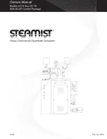
Figure 1 - Dimensional Drawing for Heavy Commercial Steam Generator (HC-9 thru HC-18)

Содержание HC-12

Страница 1: ...80 100 120 140 60 40 20 0 psi ...

Страница 2: ...ontrol Package Operation VIII Warranty information List of Illustrations Warning Sign Figure 1 Dimensional Drawing for Heavy Commercial Steam Generator HC 9 thru HC 18 Figure 2 Cables Figure 3 Typical Steam Generator Installation Figure 4 Sensor Installation Inside Steam Room Figure 5 User Control Panel Figure 6 Main Control Panel Programming Examples Specifications Chart Wiring Diagram Page 1 1 2...

Страница 3: ...nd the causes symptoms and effects of hyperthermia which may be described as follows Hyperthermia occurs when the internal temperature of the body reaches a level several degrees above the normal body temperature of 98 6 F The symptoms of hyperthermia include an increase in the internal temperature of the body dizziness lethargy drowsi ness and fainting The effects of hyperthermia include 1 Failur...

Страница 4: ...n the back of this manual C Provide an inline fuse circuit breaker as required sized in accordance with specification plate Do not install a GFI Ground Fault Interrupter to this equip ment D Select a location to install the generator to allow sufficient room See Access Area Requirements for access to the unit in the event service is required Select a clean dry indoor location protected from freezi...

Страница 5: ... an optional auto blow down assembly must be provided to route to an indirect waste 1 Rough in a water line from a cold water pipe Provide a local shut off valve 2 Rough in the steam line using 3 4 copper tubing Do NOT use iron or galvanized pipe it will rust and discolor wall of steam room For a steam line that is longer than 10 feet use an appropriate pipe insulation rated for a minimum of 212ºF...

Страница 6: ...or is designed to be used ONLY in an upright and level position to do otherwise would damage the unit and void the warranty For convenient access mount the steam generator on the optional Steamist stand designed specifically for the steam generator 1 Water supply Purge the water supply line before connecting to the steam generator In areas where high water pressure may be a problem a water hammer ...

Страница 7: ...oom 2 It is very important to pay special attention not get the connection to room 1 and room2 crossed This will be very difficult to troubleshoot If the generator is configured for one room there will not be any special markings B USER BYPASS CONTROL s The USER BYPASS CONTROL should be located outside the steam room door convenient to the bather This control gives the bather limited control of th...

Страница 8: ...o 3 separate sections SET EVENT SET VALUE and SET CLOCK The buttons on the control are grouped accordingly SET EVENT is used to set the time and day that a particular mode MAX IDLE or OFF is to begin SET VALUE is intended to set the MAX and IDLE temperature as well as the MAX CYCLE TIMER The SET CLOCK section is only for adjustment of the current time and day The DIGITAL COMMAND CENTER display lig...

Страница 9: ...l help organize your plan for the SET EVENT function The top 2 sections of the chart are filled in with 2 examples 10 08 Pub No 600 A 7 d MAX CYCLE TIMER is used to set the duration that the system will be in MAX TEMP mode after the USER BYPASS CONTROL button is pressed in It is set by pressing the corresponding button on the Digital Command Center Each time the button is pressed the minutes will ...

Страница 10: ...IDLE all day until 10PM when the club closes This would yield maximum energy savings and is the recom mended program At any time the system is in IDLE mode the user can activate the MAX TEMP mode by pressing the USER BYPASS CONTROL button Photo copy the chart and use it as a work sheet to plan you settings PROG 1 2 3 4 5 6 EXAMPLE 1 MAX IDLE OFF X X X X X X TIME 7 00AM 8 00AM 10 00AM 3 00PM 7 00PM...

Страница 11: ...utton and toggling through the programs and toggling through the days of the weeks and observing the time settings If you made no changes simply press the enter button to return to normal or it will return in 30 seconds d Programming Tip When reviewing the program and a block of days are selected if all the individual programs for those days do not match the clock will display This is normal and a...

Страница 12: ... be above the IDLE setting When all these condi tions are met then the aroma relays will energize 10 Fahrenheit and Celsius The Fahrenheit or Celsius temperature can be selected by changing a jumper in the Command Module CN109 When it is not connected open circuit it will be Fahrenheit When it is connected it will be Celsius The Jumper must be switched with power off See wiring diagram on page 11 ...

Страница 13: ...Control Fuses YL GN GN BN BK BK RD RD BK RD OR VT YL RD GY VT BN BN BK BL BL RD BK BL BN BK RD WT GY Steam1 Steam2 Heater Aroma1 Aroma2 Drain 120V 15AMP Branch Circuit H N 1 2 BK14 WT14 RD14 RD14 Pressure Limit Control F2 F1 50 Cable 50 Cable 50 Cable CN102 CN105 CN103 CN106 CN104 CN109 Back up Battery Note CN109 Jumper open F Jumper closed C Turn OFF power if making this change RD RD BK BK BN Not...

Страница 14: ......

Отзывы: