7 / 48
12
Wichtig:
Bei Unklarheiten, ob eine Durchmesseranpassung aufgrund
von Leitungstoleranzen notwendig ist, soll im Zweifel eine An-
passung durch Gummiringe bzw� Schrumpfschlauch durchge-
führt werden�
Beispiel: Nennmaß 11,1 mm +-0,3 mm ergibt 10,8 mm bis 11,4
mm: Zuordnung passt auf Typ 2 und 4 --> Messung im Detail
und Nutzung des notwendigen Zubehörs�
Important:
If it is doubtful whether a diameter adjustment is necessary
due to cable tolerances, an adjustment should be made using
rubber rings or form shroud�
Example: Nominal diameter 11�1 mm +-0�3 mm results in
10�8 mm to 11�4 mm: Allocation fits type 2 and 4 --> Measure-
ment in detail and use of the necessary accessories�
Wichtig:
Das PE-Kabel ist im Anschlussbereich über dem schwar-
zen Außenmantel mit grün-gelbem Schrumpfschlauch zu
kennzeichnen� Alternativ kann ein PE-Kabel mit grün-gelbem
Außenmantel (z�B� Typ 2) zum Einsatz kommen�
Important:
The PE cable must be marked in the connection zone with
a green-yellow shrink-on sleeve over the black outer sheath�
Alternatively, a PE cable with a green-yellow outer sheath
(e�g� type 2) can be used�
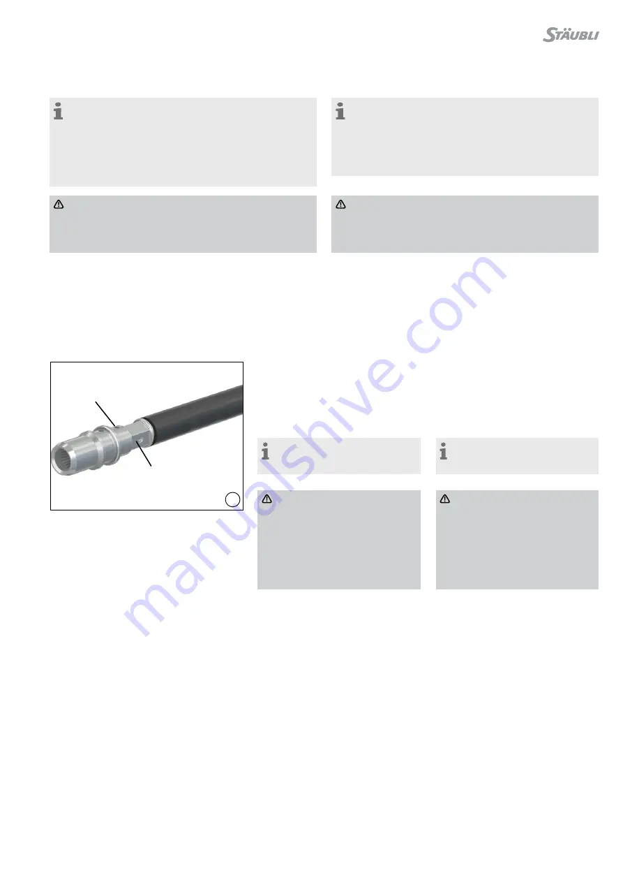
Crimpen
Crimping
(ill. 12)
Leitung in die Crimphülse einführen und
während dem Crimpen festhalten�
(ill. 12)
Insert cable into the crimping sleeve�
During the crimping operation keep on
pushing the cable into the sleeve�
Hinweis:
Litzen müssen vor dem Crimpen im
Sichtloch sichtbar sein�
Note:
Wire must be visible in the sight
hole before crimping�
Vorsicht:
AWG4 und 25 mm
2
Bündelleitung
müssen 3 Mal gecrimpt werden
(MBT11-25-50)�
Es dürfen weder vor noch nach
dem Crimpen Litzen aus der
Crimphülse hervorstehen�
Siehe Montageanleitung MA306,
www�staubli�com/electrical
Caution:
AWG4 and 25 mm
2
bundled leads
require triple crimping
(MBT11-25-50)
No wire strands must protrude
from the crimping sleeve either
before or after crimping�
See assembly instructions MA306,
www�staubli�com/electrical
Crimpbereich
Crimping zone
Sichtloch
Sight hole


