background image

24

To view manuals, videos, drivers, downloads, technical drawings, and more visit www.startech.com/support

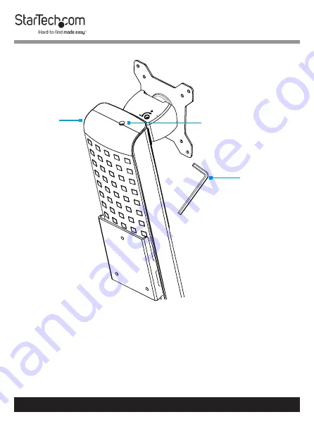
Counterbalance the Weight of the Monitor

To use the one-touch height adjustment feature, the weight of 

the 

Monitor

 must be counterbalanced with the tension of the 

One-Touch Height Adjustment Spring

• 

If the 

Monitor

 doesn’t remain in the set position, or it’s 

difficult to raise or lower, use the 

5 mm Hex Key 

to turn the


Screw

 in the top of the 

Column

 to adjust the tension of the 

One-Touch Height


Adjustment Spring

. (Figure 17

)

5 mm Hex 

Key

Adjustment Screw

Column

Figure 17

Содержание WALL-WORKSTATION-S

Страница 1: ...t information and specifications visit www StarTech com WALLSTS1 www StarTech com WALL WORKSTATION S Sit Stand Desk Wall Mount Single Monitor SKUs WALLSTS1 Black WALL WORKSTATION S Silver White User Manual Actual product may vary from photos ...

Страница 2: ... for illustrative purposes only and do not represent an endorsement of a product or service by StarTech com or an endorsement of the product s to which this manual applies by the third party company in question Regardless of any direct acknowledgement elsewhere in the body of this document StarTech com hereby acknowledges that all trademarks registered trademarks service marks and other protected ...

Страница 3: ...t être réalisé par un professionnel certifié et dans le respect des normes locales et du code de construction local 安全対策 製品の設置やマウントは 使用地域の安全ガイドラインおよび建築基準に 従い 有資格の専門業者が行うようにしてください Misure di sicurezza L installazione e o il montaggio dei prodotti devono essere eseguiti da un tecnico professionale certificato che conosca le linee guida locali sulle norme edilizie e sulla sicurezza Säkerhetsåtgärder I...

Страница 4: ... properly assembled and that the product can support the weight of the added equipment Make sure all of the equipment has been properly secured before adjusting this product Stored Energy Hazard This product contains a spring mechanism which can cause the assembly and or mounted equipment to move forcibly and quickly upwards Always exercise caution when handling or in close proximity to the spring...

Страница 5: ...g när du aktiverar handtaget Använd inte handtaget före steg 4 i installationsförfarandet När du justerar displayens höjd ska du alltid stödja eller hantera displayen med båda händerna som på bilden för att på ett säkert sätt kontrollera höjningen eller sänkningen av displayen Underlåtenhet att göra detta kan leda till egendomsskador och eller allvarliga personskador Klämrisk Håll fingrarna borta ...

Страница 6: ...bijgeleverde instructies en wees altijd voorzichtig bij het bedienen van de hendel Bedien de hendel niet vóór stap 4 van de installatieprocedure Wanneer u het scherm in hoogte verstelt moet u het scherm altijd met beide handen ondersteunen of vastpakken zoals afgebeeld om het scherm veilig omhoog of omlaag te kunnen bewegen Doet u dit niet dan kan dit leiden tot materiële schade en of ernstig pers...

Страница 7: ...esioni Capacità di carico del braccio porta monitor 2 8kg Capacità di carico del supporto per tastiera 2 5 kg Non consentire ai bambini di arrampicarsi sul prodotto o di utilizzarlo senza un adeguata supervisione Il prodotto è destinato all uso in ambienti interni Se ne sconsiglia l impiego in ambienti esterni Durante l assemblaggio del prodotto non stringere troppo le viti Se si incontra resisten...

Страница 8: ...es ou des dommages matériels Capacité de poids pour le bras d écran 2 à 8 kg Capacité de poids pour le support de clavier 2 5 kg N autorisez pas les enfants à grimper sur ce produit ni à l utiliser sans surveillance Ce produit est uniquement destiné à une utilisation en intérieur et ne doit pas être utilisé à l extérieur Ne serrez pas trop les vis lors de l assemblage de ce produit Si vous rencont...

Страница 9: ...o exterior Quando montar este produto não aperte demasiado os parafusos Se encontrar resistência enquanto aperta os parafusos pare de apertar Montar este produto é uma tarefa para duas pessoas Não tentar montar este produto e instalar o equipamento sem assistência Antes de adicionar o equipamento a este produto certifique se de que o montou e instalou devidamente e de que o produto pode suportar o...

Страница 10: ...nas para el ensamblaje de este producto No intente ensamblar este producto e instalar otros equipos sin la debida asistencia de otra persona Antes de instalar equipos en este producto asegúrese de haberlo ensamblado correctamente a fin de que pueda soportar el peso del equipo que vaya a instalar Antes de empezar a mover el carrito asegúrese de haber desbloqueado las ruedas Antes de empezar a mover...

Страница 11: ...t Versuchen Sie nicht ohne Hilfe dieses Produkt zu montieren und Geräte zu installieren Bevor Sie Geräte zu diesem Produkt hinzufügen vergewissern Sie sich dass Sie es ordnungsgemäß montiert und installiert haben und dass das Produkt das Gewicht der Geräte die Sie hinzufügen möchten tragen kann Stellen Sie sicher dass die Rollen entriegelt sind bevor Sie den Wagen in Bewegung setzen Gefahr durch g...

Страница 12: ...l Plate Side and Rear View 2 Side View 3 Keyboard Tray Top View 3 Product Information 4 Requirements 4 Package Contents 5 Installation 7 Attach the Wall Plate to a Wall 7 Attach the Monitor Arm to the Wall Plate 8 Attach the Column to the Keyboard Tray 9 Attach the Column to the Monitor Arm 10 Attach the VESA Monitor Mount to a Monitor 13 Attach the Monitor to the Column 15 Attach the Adhesive Str...

Страница 13: ...r 21 Adjust the Tilt Angle of the Monitor 22 Adjust the Tilt Angle of Keyboard Tray 23 Counterbalance the Weight of the Monitor 24 Counterbalance the Weight of the Workstation 25 Adjust the Monitor Swivel Tension 26 Extend the Keyboard Tray 27 Clean the Keyboard Tray Components 28 Warranty Information 29 Limitation of Liability 29 ...

Страница 14: ...w manuals videos drivers downloads technical drawings and more visit www startech com support Product Diagram 1 Keyboard Tray 4 Monitor Arm 2 VESA Monitor Mount 5 Cable Manager 3 Column 6 Wall Plate 1 2 3 4 5 6 ...

Страница 15: ...View Wall Plate Side and Rear View 333 mm 13 1 in 175 mm 6 9 in 672 mm 26 4 in 395 mm 15 5 in 1073 mm 42 2 in 210 mm 8 3 in 79 mm 3 1 in 50 mm 2 in 160 mm 6 3 in 124 mm 4 9 in 104 mm 4 1 in 7 mm 0 3 in 16 mm 0 6 in 13 mm 0 5 in ...

Страница 16: ... com support Side View Keyboard Tray Top View 436 mm 17 2 in 124 mm 4 9 in 926 mm 36 5 in 369 mm to 548 mm 14 5 in to 21 6 in 956 mm 37 6 in 50 5 mm 1 9 in 207 mm 8 1 in 255 mm 2 2 in 213 mm 8 4 in 668 mm 26 3 in 449 mm 17 7 in 8 mm to 217 mm 0 3 in to 8 5 in 8 mm to 217 mm 0 3 in to 8 5 in ...

Страница 17: ... WALLSTS1 www StarTech com WALL WORKSTATION S Monitor VESA Mounting Hole Pattern 75 x 75 or 100 x 100 mm Tools Pencil Phillips Head Screwdriver x 1 Ratchet inch Drive To view manuals videos drivers downloads technical drawings and more visit www startech com support To view manuals videos drivers downloads technical drawings and more visit www startech com support ...

Страница 18: ...ty 1 Column Qty 1 VESA Monitor Mount Qty 1 Wall Plate Qty 1 Adhesive Strip Qty 2 M4 x 10 mm Screws Qty 4 M6 x 8 mm Screw Qty 1 M6 x 10 mm Screws Qty 3 M6 x 12 mm Screws Qty 4 M8 x 20 mm Screws Qty 1 Mounting Screws Qty 4 Package Contents ...

Страница 19: ... a Wall Warning Wall structures vary Ensure the type of structure and mounting hardware will properly support the mounted equipment Failure to do so may result in personal injury and or equipment damage The wall should be capable of supporting at least four times the weight of the mounted equipment To view manuals videos drivers downloads technical drawings and more visit www startech com support ...

Страница 20: ...ll plate to the wall requires two people 1 Remove the Top Cover and the Bottom Cover by pinching the sides and sliding each piece away from the Wall Plate Figure 1 2 Place the Wall Plate onto the intended mounting location 3 Mark the location of the Screw Holes x 4 using a Pencil To view manuals videos drivers downloads technical drawings and more visit www startech com support Figure 1 Top Cover ...

Страница 21: ...ete Insert the Concrete Anchors x 4 into the Screw Holes x 4 7 Insert the Mounting Screws x 4 through the Wall Plate and into the Wall and tighten using a Ratchet and 8 mm Socket Attach the Monitor Arm to the Wall Plate Figure 2 Wall Plate Monitor Arm Plastic Washer Metal Washer M8 x 20 mm Screw 6 mm Hex Key To view manuals videos drivers downloads technical drawings and more visit www startech co...

Страница 22: ...on the Wall Plate 2 Place the Plastic Washer into the Joint of the Monitor Arm 3 Place the Metal Washer into the Joint of the Monitor Arm 4 Insert the M8 x 20 mm Screw through the Washers and into the Mounting Peg located on the Wall Plate and tighten using the 6 mm Hex Key Figure 2 Attach the Column to the Keyboard Tray M6x12 mm Screw 5 mm Hex Key Figure 3 ...

Страница 23: ...s located in the Keyboard Tray and into the Column and tighten using the 5 mm Hex Key Figure 12 Attach the Column to the Monitor Arm 1 Thread an M6 x 10 mm Screw into the Mounting Hole located in the top of the Plate found on the back of the Column Figure 4 Note Do not tighten the M6 x 10 mm Screw and ensure 4 to 5 mm of space is left between the Plate and the Screw Column Figure 4 To view manuals...

Страница 24: ...nical drawings and more visit www startech com support 2 Hook the M6 x 10 mm Screw attached to the Column into the Key Shaped Hole located at the top of the Plate on the Monitor Arm Figure 5 Monitor Arm Plate Key Shaped Hole M6 x 10 mm Screw Figure 5 ...

Страница 25: ...ical drawings and more visit www startech com support 3 Insert the second and third M6 x 10 mm Screws into the holes located on the Plate on the Monitor Arm and tighten using the 5 mm Hex Key Figure 6 Monitor Arm M6 x 10 mm Screw 5 mm Hex Key Figure 6 ...

Страница 26: ...d more visit www startech com support Attach the VESA Monitor Mount to a Monitor 1 To enable 360 degree rotation of the Monitor remove the Screw located in the VESA Monitor Mount using a Phillips Head Screwdriver Figure 7 Figure 7 VESA Monitor Mount Screw Screwdriver ...

Страница 27: ...4 Insert the M4 x 10 mm Screws x 4 through the VESA Monitor Mount and into the Monitor and tighten using a Phillips Head Screwdriver Figure 8 Warning Do not over tighten the Screws If resistance is experienced while tightening the Screws stop tightening To view manuals videos drivers downloads technical drawings and more visit www startech com support Bottom of Monitor VESA Monitor Mount M4 x 10 m...

Страница 28: ...nitor to the Column Note Two people are required to complete these steps safely The second person should hold the Monitor Arm to ensure it does not drop unexpectedly due to weight of the added equipment 1 Hook the back of the VESA Monitor Mount onto the Plate located on the Column Figure 9 VESA Monitor Mount Figure 9 ...

Страница 29: ...e visit www startech com support 2 Insert the M6 x 8 mm Screw through the Mounting Tab located on back of the VESA Monitor Mount and into the Plate located on the Column and tighten using the 5 mm Hex Key Figure 20 5 mm Hex Key VESA Monitor Mount M6 x 8 mm Screw Figure 10 ...

Страница 30: ... drivers downloads technical drawings and more visit www startech com support 3 Slide the Top Cover and the Bottom Cover onto the Wall Plate until each one clicks into place Figure 11 Top Cover Bottom Cover Wall Plate Figure 11 ...

Страница 31: ...the length of your Keyboard 2 Separate the two sides of the Adhesive Strip 3 Remove the Plastic Backing from the Adhesive Strip and stick it to the back of a Keyboard 4 Remove the Plastic Backing from the second Adhesive Strip and stick it to the surface of the Keyboard Tray so that it is aligned with the strip located on the Keyboard Figure 12 AdhesiveStrip Keyboard Figure 12 ...

Страница 32: ...the Cables along the Column and through the Slot located at the base of the Column 2 Squeeze the tabs located at the top of the Cable Cover and gently slide up and pull the Cable Cover off of the Monitor Arm Caution Be careful not to snap the tabs off the Cable Cover during removal Monitor Arm Cable Cable Cover Tab Tab Figure 13 ...

Страница 33: ...echnical drawings and more visit www startech com support 3 Route the Cables along the inside of the Cable Cover Figure 13 4 Squeeze the tabs located at the top of the Cable Cover and gently slide down and push the Cable Cover into the Monitor Arm ...

Страница 34: ... to move forcibly and quickly upwards Always exercise caution when handling or in close proximity to the spring arm s Do not remove the mounted equipment unless the spring arm is moved to the highest position or if pos sible the spring force is adequately lowered to remove any danger posed Failure to do so may result in property dam age and or serious personal injury 1 Disconnect all Cables attach...

Страница 35: ...Screw using the 5 mm Hex Key 3 Lift the VESA Monitor Mount off the Plate located on the Column Figure 14 Adjust the Tilt Angle of the Monitor Adjust the Screw located in the top of the VESA Monitor Mount to increase or decrease the tilt angle of the Monitor Figure 15 2 5 mm Hex Key VESA Monitor Mount Adjustment Screw Figure 15 ...

Страница 36: ...drivers downloads technical drawings and more visit www startech com support Adjust the Tilt Angle of Keyboard Tray Pull up or push down on the Keyboard Tray to adjust the angle between 0 to 90 Figure 16 Keyboard Tray Figure 16 ...

Страница 37: ...eature the weight of the Monitor must be counterbalanced with the tension of the One Touch Height Adjustment Spring If the Monitor doesn t remain in the set position or it s difficult to raise or lower use the 5 mm Hex Key to turn the Screw in the top of the Column to adjust the tension of the One Touch Height Adjustment Spring Figure 17 5 mm Hex Key Adjustment Screw Column Figure 17 ...

Страница 38: ...ure the weight of the Workstation must be counterbalanced with the tension of the One Touch Height Adjustment Spring If the Workstation doesn t remain in the set position or it s difficult to raise or lower use a Ratchet with the 8 mm Socket to turn the Screw in the hinge of the Monitor Arm to adjust the tension of the One Touch Height Adjustment Spring Figure 18 Adjustment Screw Figure 18 ...

Страница 39: ...l drawings and more visit www startech com support Figure 19 6 mm Hex Key Adjustment Screw Figure 19 Adjust the Monitor Swivel Tension Adjust the Adjustment Screw located on the base of the Monitor Arm to increase or decrease the swivel effort Figure 19 ...

Страница 40: ...drivers downloads technical drawings and more visit www startech com support Extend the Keyboard Tray Pull to extend the Extensions to the left or right of the Keyboard Tray Figure 20 Keyboard Tray Extension Extension Figure 20 ...

Страница 41: ...to extend the Extensions located on both sides of the Keyboard Tray 3 Insert a Pin into one of the two Ejection Holes located on the underside of the Keyboard Tray and pull the corresponding Extension off the Keyboard Tray Figure 22 4 Clean the Plastic Wrist Rest and Extensions in Warm Water mixed with a Non abrasive Plastic safe Cleaner Ejection Hole Extension Extension Figure 22 Wrist Rest Figur...

Страница 42: ... any damages whether direct or indirect special punitive incidental consequential or otherwise loss of profits loss of business or any pecuniary loss arising out of or related to the use of the product exceed the actual price paid for the product Somestatesdonotallowtheexclusionorlimitationofincidentalorconsequential damages If such laws apply the limitations or exclusions contained in this statem...

Страница 43: ...stered manufacturer of connectivity and technology parts StarTech com was founded in 1985 and has operations in the United States Canada the United Kingdom and Taiwan servicing a worldwide market Reviews Share your experiences using StarTech com products including product applications and setup what you love about the products and areas for improvement FR fr startech com DE de startech com ES es s...

Отзывы: