Instruction Manual
3
5. Secure the card in place using the screw you removed in Step 3.
6. When you are ready to begin the test, plug your system in and turn it on.
Using Your Card
When power is first supplied to your computer, the power supply will generate a
power good signal that is received by the motherboard clock if all the output voltages
from the power supply are correct. When the clock receives this signal, it stops forcing
a reset signal to the CPU and the CPU begins processing instructions. These initial tasks
are monitored by the circular green D1+ and D2+ LEDs. If the top D1+ LED does not
light, there is a problem with the reset. If the D2+ LED does not light, there is a problem
with the system clock.
The BIOS will then initialize, verify, and test numerous functions in your computer.
Every initialization, verification, and test is its own separate program with its own
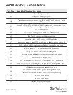
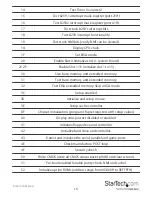
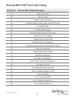
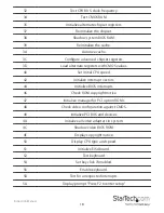
error code. As the BIOS scrolls through these processes, you will see these error codes
flashing across the LEDs. If an initialization, verification, or test fails, the system will
pause and the error code will remain on the LED. You can now consult the error code
listing and determine where the problem lies.
The error codes on the card are based on hex (0, 1, 2 ... 9, A, B, C, D, E, F, 10, 11, 12 ... 19,
1A, 1B, 1C, 1D, 1E, 1F, 20 ...) as opposed to decimal arithmetic. Therefore, a range of “2C
~ 34” means “2C, 2D, 2E, 2F, 30, 31, 32, 33, 34”.


