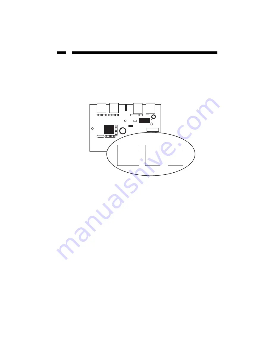
Cable Connection
Caution!!! Please take special care when inserting the cables onto the internal connectors at the
back of the panel. It is very important that the instructions below are followed carefully. Incorrect
insertion could lead to a device or motherboard short circuit.
Cable Color Diagram
1. Remove one of the brackets from the rear of the computer case. This will allow the
cables to be passed through and connected to the rear USB and IEEE 1394 ports.
2. IEEE 1394 cable: Connect the cable to the internal IEEE 1394 connector on the panel.
The connector fits on only one way, with the white wire to the right. Pass the cable
to the rear of the computer case and out the empty bracket space. Connect it to an
IEEE 1394 port on the back of the computer case.
3. USB cable: Connect the cable to the internal USB connector on the panel. The
connector fits on only one way, with the red wire to the right. Pass the cable to the
rear of the computer case and out the empty bracket space. Connect it to a USB port on
the back of the computer case.
4. Y power cable: Connect the cable to the internal power connector on the panel. Be sure
that the colored wires of the cable (from left to right) are yellow, black, black and red.
Connect one end of the connector to the power supply and the other end can be used
to attach another device.
5. Once the cables have been connected and passed through the computer case, put the
cables into the cutout slots on the bracket. Insert the bracket using the large screw
provided.
6. Once the cables have been connected to their respective rear ports, the cables can be
fixed more securely onto the panel by using the supplied screws and plastic cable
holders. Place the holder around the cable and fix it to the panel using the medium
screws provided.
7. Replace the computer case and turn on the computer.
8. Follow the software instructions as below.
1394 Port
USB B Type
Power Jack
White
Red
Y
ellow
Black Black
Red
4
Содержание 35BAYFWUSB
Страница 8: ...Revised June 11 2003...


