
Quick-Start Guide
Manual Revision: 10/11/2018
Product Design
Actual product may vary from photos
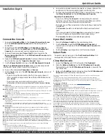
Front View
1
Handle
5
Mounting Bracket (installed)
2
Port Selection Buttons/
LEDs
6
Keyboard LEDs
3
Current Port
7
Display Menu Buttons
4
Rail(s)
8
Release Switch
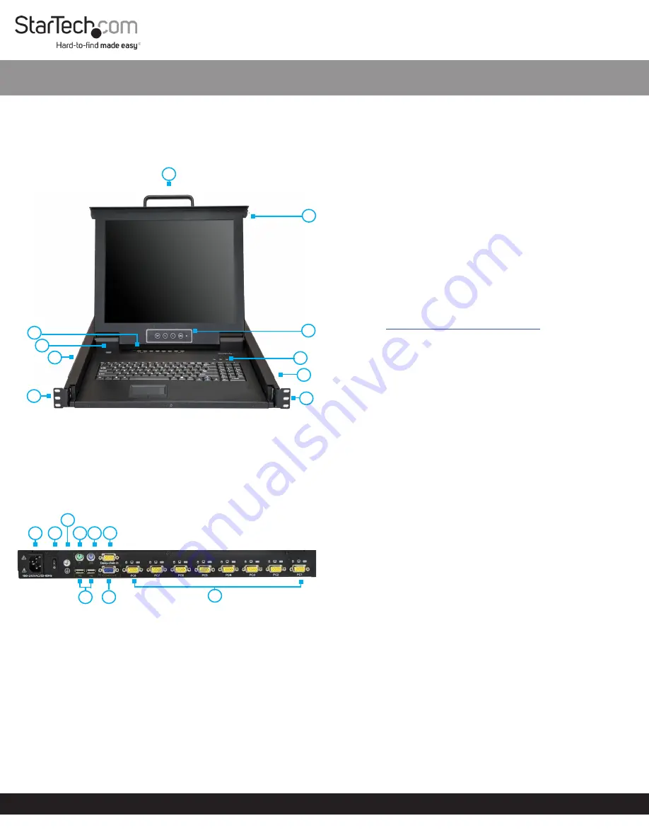
Rear View
1
Power Connection Port
6
Daisy Chain Port
2
Power Switch
7
USB-A Ports
3
Ground Connection Screw
8
Console Monitor Port
4
Console Mouse Port
9
Host Port
5
Console Keyboard Port
SKU #:
RKCONS1708K
8-Port VGA Rackmount LCD Console | 17 in | 1U
For the latest information, specifications, and support visit www.startech.com/RKCONS1708K.
Package Contents
• LCD Rackmount Console x 1
• KVM Cables x 8
• M5 Cage Nuts x 8
• M5 Screws x 8
• Regional Power Cords (NA, JP, EU, UK, ANZ) x 5
• Mounting Rails x 2
• Quick-Start Guide x 1
Requirements
• 1U of Rack Space
• Grounding Wire
• Power Source
• Up to 8 Computers or Servers
• Phillips Type Screwdriver
Requirements are subject to change. For the latest requirements,
please visit
www.StarTech.com/RKCONS1708K
.
Installation
Note:
It’s easier to install the
LCD Rackmount Console
if another
person helps you with the installation.
Warning:
Use caution and proper lifting techniques when
installing the
LCD Rackmount Console
.
1. Based on the mounting depth of the server rack that you are
using, select the appropriate length of
Mounting Rails
.
2. Decide where in the server rack you want to install the
LCD
Rackmount Console
.
3. Insert the
M5 Cage Nuts
(two per
Mounting Post
) into the
square
Mounting Holes
on the
Mounting Posts
.
4. Align the rear
Mounting Bracket Rails
with the
M5 Cage Nuts
on the corresponding
Mounting Post
.
5. Insert an
M5 Screw
(two per
Mounting Post
) through the rear
Mounting Bracket Rail
and into the
M5 Cage Nut
. Do not
tighten the
M5 Screws
.
6. With assistance, slide the
LCD Rackmount Console
into the
server rack guiding the rear
Mounting Bracket Rails
into the
Rail Assembly
.
7. Insert a
M5 Screw
(two per
Mounting Post
) through the front
Mounting Bracket Rail
into the
M5 Cage Nut
.
8. Use a
Phillips Type Screwdriver
to tighten the
M5 Screws
.
9. Ensure that the rear
Rails
are properly aligned.
10. Use a
Phillips Type Screwdriver
to tighten the
M5 Screws
.
7
2
3
6
4
5
4
5
1
2
3
4
5
6
7
8
9
1
8